Connectors (External): Difference between revisions
(→USB) |
m (→Thunderbolt) |
||
| (44 intermediate revisions by 3 users not shown) | |||
| Line 1: | Line 1: | ||
This page will help you identify many common types of | This page will help you identify many common types of plugs and sockets found on gadgets. | ||
<div class="showtoc"> | <div class="showtoc"> | ||
__TOC__ | __TOC__ | ||
| Line 6: | Line 6: | ||
==Summary== | ==Summary== | ||
There are many types of connector, which can be confusing. This page will help you identify many of them, and in some cases, indicate whether a simple adapter will enable you to connect one type to another. | There are many types of connector, which can be confusing. This page will help you identify many of them, and in some cases, indicate whether a simple adapter will enable you to connect one type to another. | ||
Here, we consider the types of connectors on the outside of gadgets. See [[Connectors (Internal)]] for those on the inside. | |||
===Safety=== | ===Safety=== | ||
| Line 11: | Line 13: | ||
::Always make sure that a connector is fully engaged. Never force it, and never pull it by the wire to unplug it. | ::Always make sure that a connector is fully engaged. Never force it, and never pull it by the wire to unplug it. | ||
<div class="mw-collapsible mw-collapsed"> | |||
<div> | |||
==Audio and Miscellaneous Connectors== | ==Audio and Miscellaneous Connectors== | ||
</div> | |||
<div class="mw-collapsible-content"> | |||
===Standard DIN=== | ===Standard DIN=== | ||
[[Image:Cherry-Schneider-MF2-5-Pin-DIN-Connector.jpg|thumb|250px|right||Five-pin male 180° DIN connector from a 1988 [[Schneider Computer Division|Schneider]] MF2 keyboard by [[Cherry (keyboards)|Cherry]]]] | [[Image:Cherry-Schneider-MF2-5-Pin-DIN-Connector.jpg|thumb|250px|right||Five-pin male 180° DIN connector from a 1988 [[Schneider Computer Division|Schneider]] MF2 keyboard by [[Cherry (keyboards)|Cherry]]]] | ||
| Line 36: | Line 43: | ||
[[File:Composite-cables.jpg|thumb|right|RCA or Phono plugs]] | [[File:Composite-cables.jpg|thumb|right|RCA or Phono plugs]] | ||
Phono, or more correctly RCA connectors are commonly used for audio and video. For stereo audio there will be two, usually red and white. See [[#Phono_2|later]] for video. | Phono, or more correctly RCA connectors are commonly used for audio and video. For stereo audio there will be two, usually red and white. See [[#Phono_2|later]] for video. | ||
They can also be used for digital audio (SPDIF), when he connectors by convention are orange. | |||
====Adapters and Compatibility==== | ====Adapters and Compatibility==== | ||
| Line 57: | Line 66: | ||
The simplest has just 2 conductors connected to the tip and the sleeve. These are designated TS. For stereo use a ring between the tip and the sleeve allows for a 3rd conductor, and these are designated TRS. The tip is normally the left channel and the ring is the right. | The simplest has just 2 conductors connected to the tip and the sleeve. These are designated TS. For stereo use a ring between the tip and the sleeve allows for a 3rd conductor, and these are designated TRS. The tip is normally the left channel and the ring is the right. | ||
To allow for a microphone as well, there is a second ring, and these jacks are designated TRRS. Combined headphone and | To allow for a microphone as well, there is a second ring, and these jacks are designated TRRS. Combined headphone and microphone sockets are common on laptops, mobile phones and tablets, but unfortunately there are two different standards for how to connect the microphone, known as CTIA and OMTP. | ||
PC microphones are generally TRS with the ring used to supply a bias voltage required by electret microphones. | PC microphones are generally TRS with the ring used to supply a bias voltage required by electret microphones. | ||
| Line 71: | Line 80: | ||
You can also get male to male and female to female adapters, and adapters with a jack connector on one end and one or two phono connectors on the other. | You can also get male to male and female to female adapters, and adapters with a jack connector on one end and one or two phono connectors on the other. | ||
===TOSLINK=== | |||
[[Image:TOS LINK clear cable.jpg|thumb|right]] | |||
TOSLINK cables and their connectors use optical fibres to carry two channels of digital audio from a source to an amplifier or recorder, usually as red light. Most use a plastic fibre which attenuates the signal and so limits the maximum length, but higher quality gass fibre cables are also available. | |||
There are also mini-TOSLINK connectors, and adapters to provide compatibility. These are almost the same size as a standard 3.5mm jack, so that the two can be combined into a single socket. | |||
<br clear=all> | |||
===XLR=== | ===XLR=== | ||
| Line 80: | Line 96: | ||
====Adapters and Compatibility==== | ====Adapters and Compatibility==== | ||
XLR to jack and phono adapters are available in all possible combinations and genders. | XLR to jack and phono adapters are available in all possible combinations and genders. | ||
===4mm Banana connectors=== | |||
[[File:4mm-plugs.png|thumb|left|Various 4mm banana plugs]] | |||
[[File:Screw terminals.jpg|thumb|right|Screw terminals also accepting banana plugs.]] | |||
4mm banana plugs and sockets are generally only rated for up to 30V since the pin may be partially exposed when not fully inserted. Nevertheless, they are frequently used for connecting test leads to a multimeter (often having ranges up to 600V), though in a variant with an insulating skirt to obviate the risk. | |||
Some banana plugs are stackable, making them useful for experimental set-ups. Higher quality gold plated versions may be encountered as loudspeaker connectors. | |||
Screw terminals are often designed to equally accept 4mm banana plugs. | |||
Smaller variants exist. A 2.6mm type is commonly used in model railways and there is also a 2mm version, optionally with an insulating skirt for higher voltage applications. | |||
<br clear=all> | |||
</div></div> | |||
<div class="mw-collapsible mw-collapsed"> | |||
<div> | |||
==Video Connectors== | ==Video Connectors== | ||
</div> | |||
<div class="mw-collapsible-content"> | |||
For a comprehensive list, see [[Wiki:List of video connectors|List of video connectors]] in Wikipedia. | For a comprehensive list, see [[Wiki:List of video connectors|List of video connectors]] in Wikipedia. | ||
| Line 117: | Line 151: | ||
A D-type connector with 15 pins in 3 rows has for many years been the standard video connector for attaching monitors and projectors to a PC or laptop. | A D-type connector with 15 pins in 3 rows has for many years been the standard video connector for attaching monitors and projectors to a PC or laptop. | ||
This carries analogue video as separate RGB plus sync signals, as well as two digital pins (data and clock) which allow a display device to indicate to the video source (PC or laptop) the resolutions and | This carries analogue video as separate RGB plus sync signals, as well as two digital pins (data and clock) which allow a display device to indicate to the video source (PC or laptop) the resolutions and refresh rates it supports, elinimating the need for manual configuration. | ||
In recent years, VGA connectors have been increasingly replaced by [[#HDMI|HDMI]], which is capable of higher quality. | In recent years, VGA connectors have been increasingly replaced by [[#HDMI|HDMI]], which is capable of higher quality. | ||
====Adapters and Compatibility==== | ====Adapters and Compatibility==== | ||
[[#HDMI|HDMI]] to VGA adapters are avaiable in order to connect a VGA projector or monitor to a laptop only supporting HDMI. (Note: since HDMI is also capable of supporting sound, a laptop may divert its audio output to the HDMI adapter, probably not what you want. Under | [[#HDMI|HDMI]] to VGA adapters are avaiable in order to connect a VGA projector or monitor to a laptop only supporting HDMI. (Note: since HDMI is also capable of supporting sound, a laptop may divert its audio output to the HDMI adapter, probably not what you want. Under Sound Settings on the laptop you should be able to select the speakers you want.) | ||
If a long cable run is required between a computer and a projector (such as in a school church or public hall) then the signal may be degraded. Special adapters are | If a long cable run is required between a computer and a projector (such as in a school, church or public hall) then the signal may be degraded. Special adapters are available to convert the signal to a form that can be carried over standard network cable using RJ45 connectors, over much greater distances and if required, to multiple display devices. The better ones require power in order to actively restore the signal at the receiving end. | ||
Some older high quality monitors accept VGA input via 5 [[#BNC|BNC]] connectors. You can get a cable with a standard VGA plug on one end and the 5 BNC plugs on the other. | Some older high quality monitors accept VGA input via 5 [[#BNC|BNC]] connectors. You can get a cable with a standard VGA plug on one end and the 5 BNC plugs on the other. | ||
| Line 142: | Line 176: | ||
Passive adapters are available to connect a DVI-I or DVI-D source to HDMI display. | Passive adapters are available to connect a DVI-I or DVI-D source to HDMI display. | ||
Although an HDMI alternate mode is defined for USB-C, no known products implement this, so it's not possible to connect a USB-C source to an HDMI display. | Although an HDMI alternate mode is defined for USB-C, no known products implement this, so it's not urrently possible to connect a USB-C source to an HDMI display. | ||
<br clear=all> | <br clear=all> | ||
| Line 162: | Line 196: | ||
[[File:Displayport-cable.jpg|thumb|right|DisplayPort connector]] | [[File:Displayport-cable.jpg|thumb|right|DisplayPort connector]] | ||
[[File:Mdp plug.jpg|Mini DisplayPort plug|thumb|right]] | [[File:Mdp plug.jpg|Mini DisplayPort plug|thumb|right]] | ||
DisplayPort is a highly versatile digital video and audio interface. The standard plug and socket are rectangular with with one corner bevelled. A mini version used on Apple computers is smaller and | DisplayPort is a highly versatile digital video and audio interface. The standard plug and socket are rectangular with with one corner bevelled. A mini version used on Apple computers is smaller and more squat, with two corners bevelled. | ||
Subject to support by the operating system, DisplayPort can drive multiple displays, daisy-chained together. This is achieved either with a DisplayPort hub or a DisplayPort output on (at least) the first display. This facility is known as Multi-Stream Transport, or MST. This is supported by Windows but not by MacOS as of macOS 10.15 ("Catalina"). | Subject to support by the operating system, DisplayPort can drive multiple displays, daisy-chained together. This is achieved either with a DisplayPort hub or a DisplayPort output on (at least) the first display. This facility is known as Multi-Stream Transport, or MST. This is supported by Windows but not by MacOS as of macOS 10.15 ("Catalina"). | ||
| Line 173: | Line 207: | ||
DisplayPort Dual Mod (DP++) allows DisplayPort sources to use simple passive adapters to connect to HDMI or DVI displays. Such sources should bear a DP++ logo though many don't, in which case you'd need to consult the specifications. | DisplayPort Dual Mod (DP++) allows DisplayPort sources to use simple passive adapters to connect to HDMI or DVI displays. Such sources should bear a DP++ logo though many don't, in which case you'd need to consult the specifications. | ||
<br clear=all> | <br clear=all> | ||
</div></div> | |||
==RF== | <div class="mw-collapsible mw-collapsed"> | ||
<div> | |||
==RF Connectors== | |||
</div> | |||
<div class="mw-collapsible-content"> | |||
RF connectors are used to connect an aerial to a receiver or a transmitter, or more generally for high frequency (usually) analogue signals. | RF connectors are used to connect an aerial to a receiver or a transmitter, or more generally for high frequency (usually) analogue signals. | ||
At these frequencies, cables, connectors, aerials, tuner inputs and transmitter outputs etc all have a "characteristic impedance" which must match for best results. | At these frequencies, cables, connectors, aerials, tuner inputs and transmitter outputs etc all have a "characteristic impedance" which must match for best results. | ||
To understand this, supposing you had a 3,000 mile long transatlantic cable and you connected a battery to one end and a bulb to the other. Since nothing can travel faster than light, after connecting the battery, it'll take around 15mS for the electricity to reach the bulb. During that time the battery won't know even whether there is a bulb at the other end! So how does it know how much current to send? In fact any cable has a "characteristic impedance" determined by the size and separation of the conductors, and which determines how much current it will accept for a given voltage. If that's different from the amount the bulb can accept (the bulb's impedance) | To understand this, supposing you had a 3,000 mile long transatlantic cable and you connected a battery to one end and a bulb to the other. Since nothing can travel faster than light, after connecting the battery, it'll take around 15mS for the electricity to reach the bulb. During that time the battery won't know even whether there is a bulb at the other end! So how does it know how much current to send? In fact any cable has a "characteristic impedance" determined by the size and separation of the conductors, and which determines how much current it will accept for a given voltage. If that's different from the amount the bulb can accept (the bulb's impedance) then the balance will be reflected back down the cable. That is sub-optimal, and to be avoided. In the case of a high power transmitter with a mis-matched aerial, the transmitter will be upset and may be seriously damaged, if half its ouput power comes straight back down the line and hits it in the face! | ||
The fact that air and glass have different characteristic impedances to light waves (related to their refractive indices) is why you can see your reflection in a window. | |||
=== Belling-Lee TV Aerial plug=== | === Belling-Lee TV Aerial plug=== | ||
| Line 186: | Line 229: | ||
Its characteristic impedance is 75Ω and should be used with 75Ω coaxial cable. | Its characteristic impedance is 75Ω and should be used with 75Ω coaxial cable. | ||
<br clear=all> | |||
=== Motorola connector === | |||
[[File:Motorola Plug.png|thumb|right|A Motorola car radio aerial connector.]] | |||
You will often see this type of connector on a car radio. A springy section allong the the length of the shell of the plug ensures a good connection. Like the Belling-Lee, it has a 75Ω characteristic impedance. | |||
<br clear=all> | <br clear=all> | ||
| Line 191: | Line 239: | ||
[[File:F-Stecker_und_Kabel.jpg|thumb|right|A male F connector]] | [[File:F-Stecker_und_Kabel.jpg|thumb|right|A male F connector]] | ||
F connectors are used for cable and satellite TV and also have a 75Ω characteristic impedance. The centre conductor of the cable forms the pin and a captive threaded nut secures the connector to a socket and makes the connection for the shield. | F connectors are used for cable and satellite TV and also have a 75Ω characteristic impedance. The centre conductor of the cable forms the pin and a captive threaded nut secures the connector to a socket and makes the connection for the shield. | ||
A smaller version of the plug is designed for thinner more flexible cable which can be used in short runs, but still mating with the same sockets. If you're fitting your own plugs, it's important to select the size of plug which matches the diameter of the cable. | |||
Adapters are available to interconnect F and Belling-Lee connectors. An F coupler allows two F plugs to be connected together, for example if you had two cables with F plugs, each half the length you need. | |||
<br clear=all> | <br clear=all> | ||
| Line 197: | Line 249: | ||
BNC connectors are very widely used in professional test and measurement and many other kinds of equipment for connecting items together and for attaching test probes. Standard BNC connectors are 50Ω but a slightly larger 75Ω version also exists. They are used in some high end monitors for component video and formerly were widely used in computer networking. | BNC connectors are very widely used in professional test and measurement and many other kinds of equipment for connecting items together and for attaching test probes. Standard BNC connectors are 50Ω but a slightly larger 75Ω version also exists. They are used in some high end monitors for component video and formerly were widely used in computer networking. | ||
<br clear=all> | <br clear=all> | ||
===SMA=== | |||
[[File:Male 50 ohm SMA connector.jpg|thumb|right|A male 50Ω SMA connector.]] | |||
SMA is a miniature 50Ω connector, the socket having a 1/4" diameter thread. The aerials on your WiFi router may be attached with this kind of connector, and you might find it on an external aerial for a satnav. | |||
===Other ham radio and professional=== | |||
There are a few [[wiki:List_of_RF_connector_types|other types]] common on professional and ham radio equipment, but which will rarely be seen in a community repair event. | |||
<br clear=all> | |||
</div></div> | |||
<div class="mw-collapsible mw-collapsed"> | |||
<div> | |||
==Data Connectors== | ==Data Connectors== | ||
</div> | |||
<div class="mw-collapsible-content"> | |||
===D Subminiature=== | ===D Subminiature=== | ||
[[Image:Dsubs.png|thumb|A 9-pin male connector, and a 25-pin female connector.]] | [[Image:Dsubs.png|thumb|A 9-pin male connector, and a 25-pin female connector.]] | ||
| Line 263: | Line 329: | ||
A yellow tongue indicates that this USB port is powered even when the laptop is shut down, and so can be used for charging, whether or not the laptop is in use. | A yellow tongue indicates that this USB port is powered even when the laptop is shut down, and so can be used for charging, whether or not the laptop is in use. | ||
The micro USB plug was introduced to supersede the mini version, which was perceived to have reliability problems. In fact the micro version has its own problems in that the commonly seen surface mount micro USB socket is easily pulled off the circuit board if an upward force is applied to the plug, whether through an accident or clumsiness. This can be challenging to repair, especially if the circuit traces have also lifted from the board. | |||
<br clear=all> | <br clear=all> | ||
| Line 287: | Line 355: | ||
<br clear=all> | <br clear=all> | ||
=== | ===FireWire (IEEE 1494)=== | ||
[[File:FireWire symbol.svg|30px|left]] | [[File:FireWire symbol.svg|30px|left]] | ||
[[File:FireWire800 Stecker.jpeg|thumb|A 9-pin FireWire 800 connector]][[File:FireWire cables.jpg|thumb|4-conductor (left) and 6-conductor (right) FireWire 400 alpha connectors]] | [[File:FireWire800 Stecker.jpeg|thumb|A 9-pin FireWire 800 connector]][[File:FireWire cables.jpg|thumb|4-conductor (left) and 6-conductor (right) FireWire 400 alpha connectors]] | ||
Firewire, or IEEE 1594, | Firewire, or IEEE 1594, is used for high speed data transfer, most frequently audio and video data. It is not dissimilar to USB and predates it, but has achieved far less marketshare. Unlike USB which requires one device to act as a host, FireWire adopts a peer to peer architecture in which devices cooperate amongst themselves. This allows (for example) a scanner to talk to a printer without the mediation of a computer, or a camcorder to talk equally to a computer or directly to a display. | ||
A port provides power but this is unregulated, nominally 24 - 30V but can fall as low as 9V on battery powered devices. | |||
FireWire appeared on Apple Mac computers in the first decade of this century but has since been superceded by Thunderbolt. | |||
There are several versions of FireWire: | |||
* FireWire 400 (IEEE 1394-1995) supports data rates up to 400Mbps and uses a 6 pin connector. | |||
* IEEE 1394a-2000 is an improvement on FireWire 400, using the avaiable bandwidth more efficiently and using a 4 pin connector. | |||
* FireWire 800 (IEEE 1394b-2002) offers a doubling of the bit rate, using a 9 pin connector. | |||
* FireWire S1600 and S3200 use the same 9 pin connector but the only products to have been released using this standard are som Sony cameras. | |||
A FireWire device is able to directly access the main memmory of a computer, enabling you to transfer data in bulk without the cooperation of the processor. However, this does present a security risk. Even though your unattended Windows computer might be logged out, an attacker could use the FireWire port to extract the entire contents of memory, including any private data and cryptographic keys it might find. | |||
====Adapters and Compatibility==== | |||
FireWire versions are generally bckwards compatible. A "bilingual" cable can be used with both 6 and 9 pin ports. | |||
Firewire/Tunderbolt adapters allow legacy FireWire devices to be used with the more modern Tunderbolt system. You can also get USB to FireWire adapters. | |||
<br clear=all> | <br clear=all> | ||
===Thunderbolt=== | ===Thunderbolt=== | ||
[[File:Thunderbolt Symbol.svg|left|15px]] | |||
[[File:Thunderbolt-Connector.jpg|thumb|250px|Thunderbolt 1 or 2, connector]] | [[File:Thunderbolt-Connector.jpg|thumb|250px|Thunderbolt 1 or 2, connector]] | ||
[[File:Apple MacBook Pro, model A1278-8118.jpg|thumb|250x250px|Thunderbolt 1 or 2, port]] | [[File:Apple MacBook Pro, model A1278-8118.jpg|thumb|250x250px|Thunderbolt 1 or 2, port]] | ||
Thunderbolt was introduced in 2009 as Light Peak, originally conceived to use optical cables. It combines PCI Express and DisplayPort, and additionally provides power (though not with optical cables). Thunderbolt 1 and 2 use the same connector as Mini DisplayPort whereas Thunderbolt 3 and 4 use a USB-C connector. | |||
Thunderbolt 1 has a data rate of 10Gbps, which is doubled in Thunderbolt 2, though Thunderbolt 1 and 2 devices are compatibe and use the same cables and connectors. | |||
Thunderbolt 3 and 4 increase the data rate further to 40Gbps. Thunderbolt 4 additionally offers protection against the direct memory access attacks that Firewire and earliier Thunderbolt versions are susceptible to. It can also use Thunderbolt Alternate Mode USB-C hubs. | |||
====Adapters and Compatibility==== | |||
Adapters are available to allow Thuderbolt 1/2 devices to be driven from a Thunderbolt 3/4 (USB-C) port, also to allow a Thunderbolt port to be connected to FireWire and HDMI devices. | |||
<br clear=all> | <br clear=all> | ||
===Apple Lightning=== | ===Apple Lightning=== | ||
[[File:Lightning to USB Cable.jpg|thumb|right|Apple Lightning to USB cable (MD818)]] | [[File:Lightning to USB Cable.jpg|thumb|right|Apple Lightning to USB cable (MD818)]] | ||
Lightning is Apple's proprietary connector for connecting chargers and accessories to iPhones, iPads and iPods, superceding the 30 pin connector in 2012. It uses USB 2 but doesn't support OTG. Later devices starting in 2015 use USB 3 and can act as host, but a camera adapter is the only supported device. | |||
====Adapters and Compatibility==== | |||
Lightning adapters are available for connecting headphones (in the absence of an in-built headphone port), microphones and HDMI displays. For Apple devices supporting USB 3 OTG, adapters allow the connection of cameras, memory cards and memory sticks, as well as other USB devices, subject to support by iOS. | |||
<br clear=all> | <br clear=all> | ||
===Apple 30 pin=== | ===Apple 30 pin=== | ||
[[File:Apple Dock Connector.jpg|150px]] | [[File:Apple Dock Connector.jpg|150px|right]] | ||
The Apple 30 pin connector appeard on iPhones, iPads and iPods until superceded by the much more compact Lightning connector. Each of many different functions are carried on separate pins, not all used on all devices. | |||
====Adapters and Compatibility==== | |||
If you have one of those iPod docks which were popular at the time, you can get a Lightning to 30 pin adapter to use it to play music from your iPhone. | |||
<br clear=all> | <br clear=all> | ||
</div></div> | |||
<div class="mw-collapsible mw-collapsed"> | |||
<div> | |||
==Power Connectors== | ==Power Connectors== | ||
</div> | |||
<div class="mw-collapsible-content"> | |||
===Mains connectors=== | ===Mains connectors=== | ||
[[File:Mains connectors.jpg|thumb|right|Figure of 8, clover leaf and IEC mains connectors.]] | [[File:Mains connectors.jpg|thumb|right|Figure of 8, clover leaf and IEC mains connectors.]] | ||
Many mains powered devices such as desktop computers, laptop power adapters, TVs and audio equipment have detachable power leads of one of three types, shown in the photo. | Many mains powered devices such as desktop computers, laptop power adapters, TVs and audio equipment have detachable power leads of one of three types, shown in the photo. | ||
The figure of 8 connector is used for double-insulated devices (indicated by a symbol consisting of two squares, one inside the other). The mains plug on the | The figure of 8 connector is used for double-insulated devices (indicated by a symbol consisting of two squares, one inside the other). The mains plug on the other end will usually have a plastic earth pin (the larger one) and the lead is likely to be flat since it contains just two wires side by side. | ||
Clover leaf and IEC leads are used for earthed devices. There may be no accessible metal parts to earth, but even if not there will be an earthed internal metal frame. | Clover leaf and IEC leads are used for earthed devices. There may be no accessible metal parts to earth, but even if not there will be an earthed internal metal frame. | ||
An IEC connector is essentially the same as a kettle lead, except that a kettle lead connector has a | An IEC connector is essentially the same as a kettle lead, except that a kettle lead connector has a depression on the flat side to accommodate a ridge in the socket. This prevents an IEC lead from being used with a kettle, which would overload it, but you can if you like use a kettle lead in a device with an IEC mains inlet. | ||
You can get adapters to allow you to use an IEC lead with a device having a clover leaf mains inlet and vice versa, and also to allow either a clover leaf or IEC lead to be used to power a device with figure of eight inlet but not the reverse, as the device would not then be earthed. | |||
<br clear=all> | |||
===Low voltage power connectors=== | |||
[[File:Low voltage power tips.jpg|thumb|right]] | |||
There are numerous types of low voltage power connectors used by any device with a separate mains power adaptor or charger. The photo shows a set of tips to fit on a universal lead. | |||
The circular ones have a designation such as 5.5x2.1, indicating the external diameter of the plug, and the diameter of the central pin, both in mm. | |||
5.5x2.1 and 5.5x2.5 are perhaps the commonest but are hard to tell apart visually. The only sure way is to try both types of plug in a given socket. A 5.5x2.5 plug will fit in a 5.5x2.1 socket, if a little loosely, but not the reverse. | |||
Typically, the centre pin will be positive but very occasionally you might find it's negative, so always check. Sets of tips can often be connected either way to a universal lead, and universal adapters may have a polarity switch or may even be [[Glossary:AC|AC]] instead of [[Glossary:DC|DC]]! Also the voltage required by the device and supplied by the adapter may be different so check this too. Getting the polarity or the voltage wrong can destroy your gadget, so beware! Always check markings and if in doubt, check the voltage and polarity with a [[How_to_use_a_multimeter|multimeter]]. | |||
<br clear=all> | <br clear=all> | ||
===Laptop power connectors=== | ===Laptop power connectors=== | ||
Unfortunately there is little or no standardisation amongst laptop power connectors nor of the voltages laptops require. Most laptop power supplies produce between 18 and 20V and have a round connector. | |||
Some manufacturers such as Dell and Lenovo use the same adapter type across a wide range of laptops, though often with divergences amongst consumer grade products. For a number of years Lenovo have used a round connector but more recently have moved to a rectangular one similar in size to a USB plug. Fortunately, adapters are available allowing you to use an old Lenovo adapter with a newer laptop (or vice versa). | |||
[[File:MagSafe1.jpg|thumb|right|Apple MagSafe (Original) connector.]] | |||
Some Apple MacBooks use the MagSafe magnetically-attached power connector. There have been three variants of this: MagSafe 1, 2 and 3, each smaller than its predecessor. The idea of a magnetically attached power cable is derived from deep fryers and other cooking appliances where tripping over the power cable could result in a dangerous spill of hot liquid. The MagSafe conector similarly averts the risk of a laptop being pulled off a desk if someone trips on the power cable. | |||
A MagSafe connector can be attached either way round. It has 5 pins, the outer pair being ground and the next pair being power. The small central pin is used for signalling, allowing the laptop to determine the power rating of the adapter and to control the LED in the connector, however, only power and ground are connected through the cable to the adapter body. | |||
Problems with the cable insulation cracking are common and can lead to overheating and potentially a risk of fire. Particularly vulnerable are the points where the cable enters the MagSafe connector or the adapter body, and these should be protected with [https://sugru.com Sugru] before the deterioration starts to affect the insulation on the two wires within the outer sheath. | |||
<br clear=all> | <br clear=all> | ||
< | ===USB=== | ||
USB delivers power at 5V and up to 1A as standard, more in the case of USB C. Hence this is an attractive option for powering or charging a variety of devices beyond smartphones and tablets, and is becoming common on ultra-ythin laptops. | |||
Use of Micro USB is common (Mini USB on older devices), and we can expect to see USB C increasingly as the preferred method following moves in the European Union to mandate this in order to reduce the e-waste resulting from the proliferation of chargers. | |||
</div></div> | |||
==External Links== | |||
* [https://web.archive.org/web/20060301104534/http://www.hardwarebook.net/download/index.html The Hardware Book] (download from [https://web.archive.org The Wayback Machine]) contains details of many legacy connectors such as those used on home and personal computers from the 1980's and 90's, including serial and parallel cables and adapters which you might need for an old printer, scanner or modem. | |||
* [http://connectorbook.com/ The Electronic Connector Book] (website and hard-copy book) contains an exhaustive list of hundreds of types of connector. | |||
[[Category:General]] | [[Category:General]] | ||
Latest revision as of 07:39, 13 October 2024
This page will help you identify many common types of plugs and sockets found on gadgets.
Summary
There are many types of connector, which can be confusing. This page will help you identify many of them, and in some cases, indicate whether a simple adapter will enable you to connect one type to another.
Here, we consider the types of connectors on the outside of gadgets. See Connectors (Internal) for those on the inside.
Safety
- Always make sure that a connector is fully engaged. Never force it, and never pull it by the wire to unplug it.
Audio and Miscellaneous Connectors
Standard DIN
DIN connectors are primarily intended for analogue audio. The commonest are the 5-pin type which were often seen on cassette recorders when they were still much in use. The 5 pins were used for left and right, record and playback, plus ground return.
The same connector is still seen on digital musical instruments such as keyboards where they are used for MIDI. (Note that the MIDI lead marked Out goes into the socket marked In and the lead mark In into the socket marked Out.)
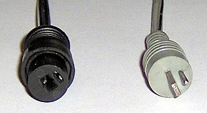
Different versions having from 3 to 8 pins are sometimes seen, occasionally as a power connector or for various other uses. DIN lounspeaker
A DIN loudspeaker connector is the same size but has just two pins, one of which is flat. This is sometimes used as a power connector on Christmas lights.
Mini-DIN

This type of connector has been used for various purposes. Like the standard DIN, it comes in various configurations from 3 to 9 pins. In the 6 pin variant it's mostly remembered today as the standard PS/2 PC keyboard and mouse connector before USB became the norm. Early USB keyboards and mice often came with a USB to PS/2 adapter. These didn't convert USB to PS/2 - such keyboards simply sensed which protocol to talk by the voltages it sensed o the USB plug.
Older laptops sometimes had a 4-pin mini DIN socket for S-video output (see later).
Note that the pins in a mini-DIN connector are quite thin and easily bent. With care, they can be straightened but risk breaking off.
Phono
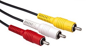
Phono, or more correctly RCA connectors are commonly used for audio and video. For stereo audio there will be two, usually red and white. See later for video.
They can also be used for digital audio (SPDIF), when he connectors by convention are orange.
Adapters and Compatibility
Audio leads are available to connect two phono connectors to a stereo jack connector.
Video leads or adapter allow you to connect between VGA or SCART connectors and phono connectors.
Jack
Jack (or phone) connectors have an ancestry going back well over 100 years, having first been designed for telephone systems. They have the great advantage that, being round, there is no correct or incorrect orientation in order to get them to mate, making it very quick and easy for a manual telephone switchboard operator to connect a caller.
Modern versions come in 3 sizes: standard 6.35mm (or 1/4"), 3.5mm miniature and 2.5mm sub-miniature, all used almost exclusively for audio, mainly headphones and microphones.
The simplest has just 2 conductors connected to the tip and the sleeve. These are designated TS. For stereo use a ring between the tip and the sleeve allows for a 3rd conductor, and these are designated TRS. The tip is normally the left channel and the ring is the right.
To allow for a microphone as well, there is a second ring, and these jacks are designated TRRS. Combined headphone and microphone sockets are common on laptops, mobile phones and tablets, but unfortunately there are two different standards for how to connect the microphone, known as CTIA and OMTP.
PC microphones are generally TRS with the ring used to supply a bias voltage required by electret microphones.
TRRRS jacks exist but are unusual. The extra ring can be used for a second microphone or for supplying power.
3.5mm jacks are sometimes used for video, but beware: these may have a 17mm shaft which could damage a socket designed for the more usual 15mm jacks if forced in.
Adapters and Compatibility
Adapters are available for any of the three common sizes to any other, and in the various TS, TRS etc variants. If you want to connect a mono source to a stereo input or vice versa you'll need a correctly wired adapter (or make one up yourself). A headphone splitter allows two 3.5mm headphone jacks to share the output from one 3.5mm headphone socket.
If you need to connected headphones and a separate microphone to a combined socket you can get a suitable adapter with a TRRS plug on one end and two TRRS sockets one for the headphone and the other for he microphone, on the other. But there are two types: CTIA and OMTP. The specification for your laptop should tell you which you need.
You can also get male to male and female to female adapters, and adapters with a jack connector on one end and one or two phono connectors on the other.
TOSLINK
TOSLINK cables and their connectors use optical fibres to carry two channels of digital audio from a source to an amplifier or recorder, usually as red light. Most use a plastic fibre which attenuates the signal and so limits the maximum length, but higher quality gass fibre cables are also available.
There are also mini-TOSLINK connectors, and adapters to provide compatibility. These are almost the same size as a standard 3.5mm jack, so that the two can be combined into a single socket.
XLR
XLR connectors are very commonly used for better quality microphones, and audio connections more generally. For these applications they have 3 pins, though other variants exist. The 3 pins allow for balanced audio, that's to say, two of the pins carry the same audio signal but in opposite phase. At the receiving end the equipment doesn't respond to the absolute level of either, but the difference between the two. Any interference picked up along a cable run will be picked up equally in the same phase by both conductors and hence will be cancelled out by the receiving eqipment.
5-pin XLR connectors are used on DMX stage lighting control systems.
Adapters and Compatibility
XLR to jack and phono adapters are available in all possible combinations and genders.
4mm Banana connectors
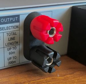
4mm banana plugs and sockets are generally only rated for up to 30V since the pin may be partially exposed when not fully inserted. Nevertheless, they are frequently used for connecting test leads to a multimeter (often having ranges up to 600V), though in a variant with an insulating skirt to obviate the risk.
Some banana plugs are stackable, making them useful for experimental set-ups. Higher quality gold plated versions may be encountered as loudspeaker connectors.
Screw terminals are often designed to equally accept 4mm banana plugs.
Smaller variants exist. A 2.6mm type is commonly used in model railways and there is also a 2mm version, optionally with an insulating skirt for higher voltage applications.
Video Connectors
For a comprehensive list, see List of video connectors in Wikipedia.
Colour encoding
There are several ways of communicating an analogue colour video signal, using one or several separate wires and connector pins.
Component video uses three separate connections for the colour signal, and maybe two more for horizontal and vertical sync. The simplest to understand is RGB, where the red, green and blue signals are carried on separate connector pins. Horizontal and vertical sync signals may be carried on two more pins.
YPbPr is another component video scheme allowing easy compatibility with monochrome TVs and is hence use for analogue broadcast TV. Here, the Y carries the brightness (technical term: luminance), effectively the monochrome used by a black and white TV. Pb then carries the blue and Pr the red. If you subtract the blue and red from the brightness, all that's left has got to be just the green.
S-video, by contrast, carries the luminance combined with horizontal and vertical sync on one pin, and all the colour information (chrominance and saturation) cunningly combined on another. Audio is carried separately.
Composite video combines both of the S-video signals into a single channel, with some slight loss of quality. This is how analogue broadcast TV works. As with S-video, audio is carried separately.
Phono
Phono plugs (see above) may be used for analogue video. There may be a single yellow connector for composite video, or red, green and blue for component video, and perhaps yellow and white for horizontal and vertical sync.
SCART
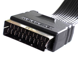
SCART connectors (also known as Péritel, especially in France) have been around since video recorders first became affortable. It can carry analogue video as RGB, YPbPr or S-video and stereo sound. Some of those video formats can be carried in both directions (one at a time). In addition, it carries signalling, allowing a connected device to indicate that it's active. For example, this allows a video recorder to switch on a TV and display its output when the user presses Play.
Adapters and Compatibility
Adapters are available to convert video and audio output from a scart socket to phono sockets. It is also possible to convert a SCART output to VGA, though differences in the voltage levels used for the sync signals may mean an active coverter is required, containing minimal electronics.
Mini-DIN
Mini-DIN connectors (see above) in the 4-pin format may be used for S-video. These are quite often seen on older laptops.
Adapters and Compatibility
Adapters are available to convert S-video on a Mini DIN connector to composite video on a phono connector.
VGA
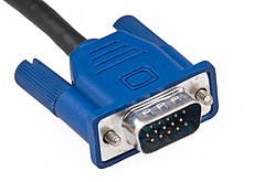
A D-type connector with 15 pins in 3 rows has for many years been the standard video connector for attaching monitors and projectors to a PC or laptop.
This carries analogue video as separate RGB plus sync signals, as well as two digital pins (data and clock) which allow a display device to indicate to the video source (PC or laptop) the resolutions and refresh rates it supports, elinimating the need for manual configuration.
In recent years, VGA connectors have been increasingly replaced by HDMI, which is capable of higher quality.
Adapters and Compatibility
HDMI to VGA adapters are avaiable in order to connect a VGA projector or monitor to a laptop only supporting HDMI. (Note: since HDMI is also capable of supporting sound, a laptop may divert its audio output to the HDMI adapter, probably not what you want. Under Sound Settings on the laptop you should be able to select the speakers you want.)
If a long cable run is required between a computer and a projector (such as in a school, church or public hall) then the signal may be degraded. Special adapters are available to convert the signal to a form that can be carried over standard network cable using RJ45 connectors, over much greater distances and if required, to multiple display devices. The better ones require power in order to actively restore the signal at the receiving end.
Some older high quality monitors accept VGA input via 5 BNC connectors. You can get a cable with a standard VGA plug on one end and the 5 BNC plugs on the other.
HDMI
HDMI connectors are used for digital video and audio and are very common on modern audio-visual equiment and laptops, especially consumer laptops. They are largely superceding the older VGA type of connector, giving higher quality.
There are three sizes of connector: standard, mini and micro, 13.9, 10.42 and 5.83mm wide. All are very much the same shape and have the same number of pins. At a glance, the micro-HDMI connector could be mistaken for micro-USB, but is slightly narrower and fatter.
Like VGA, HDMI uses two of the pins for a data channel, which a display device can use to communicate its capabilities to the video source. This data channel can also be used for digital rights management.
Adapters an Compatibility
Adapters are readily avalable enabling all three sizes to be interconnected.
Passive adapters are available to connect a DVI-I or DVI-D source to HDMI display.
Although an HDMI alternate mode is defined for USB-C, no known products implement this, so it's not urrently possible to connect a USB-C source to an HDMI display.
DVI
DVI has several variants which can carry digital video (DVI-D), analogue video (DVI-A) or both (DVI-I).
The digital signals are carried on 24 pins in 3 rows. A lower bandwidth version has a block of 9 pins missing in the middle, and a dual channel version has 30 pins in 3 rows.
Analogue video is carried on 4 pins in a square plus a spade between them for ground return. These are not present in the photo, only a slot for the spade.
Adapters and Compatibility
The analogue signals in DVI-A and DVI-I are comptible with VGA, so a passive adapter can be used to convert between the two.
Similarly, the digital signals in DVI-D and DVI-I are compatible with HDMI with some limitations (protected content from an HDMI source can't be played on a DVI device) so passive adapters can be used to convert both ways.
DisplayPort
DisplayPort is a highly versatile digital video and audio interface. The standard plug and socket are rectangular with with one corner bevelled. A mini version used on Apple computers is smaller and more squat, with two corners bevelled.
Subject to support by the operating system, DisplayPort can drive multiple displays, daisy-chained together. This is achieved either with a DisplayPort hub or a DisplayPort output on (at least) the first display. This facility is known as Multi-Stream Transport, or MST. This is supported by Windows but not by MacOS as of macOS 10.15 ("Catalina").
DisplayPort can also carry a USB channel. Conversely, USB-C can carry DisplayPort signals, allowing a DisplayPort device to be driven from a USB-C source using a suitable cable, provided it's supported by the source.
DisplayPort cables come in different grades, a higher grade being required for higher resolutions and refresh rates.
Adapters and Compatibilty
DisplayPort Dual Mod (DP++) allows DisplayPort sources to use simple passive adapters to connect to HDMI or DVI displays. Such sources should bear a DP++ logo though many don't, in which case you'd need to consult the specifications.
RF Connectors
RF connectors are used to connect an aerial to a receiver or a transmitter, or more generally for high frequency (usually) analogue signals.
At these frequencies, cables, connectors, aerials, tuner inputs and transmitter outputs etc all have a "characteristic impedance" which must match for best results.
To understand this, supposing you had a 3,000 mile long transatlantic cable and you connected a battery to one end and a bulb to the other. Since nothing can travel faster than light, after connecting the battery, it'll take around 15mS for the electricity to reach the bulb. During that time the battery won't know even whether there is a bulb at the other end! So how does it know how much current to send? In fact any cable has a "characteristic impedance" determined by the size and separation of the conductors, and which determines how much current it will accept for a given voltage. If that's different from the amount the bulb can accept (the bulb's impedance) then the balance will be reflected back down the cable. That is sub-optimal, and to be avoided. In the case of a high power transmitter with a mis-matched aerial, the transmitter will be upset and may be seriously damaged, if half its ouput power comes straight back down the line and hits it in the face!
The fact that air and glass have different characteristic impedances to light waves (related to their refractive indices) is why you can see your reflection in a window.
Belling-Lee TV Aerial plug
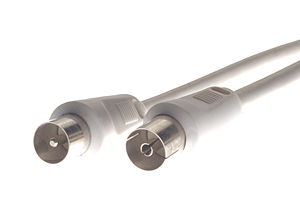
This type of plug is very widely used in Europe and Australia for connecting aerials to TVs and FM radio tuners. Double-ended female adapters are available for connecting two male plugs.
Its characteristic impedance is 75Ω and should be used with 75Ω coaxial cable.
Motorola connector
You will often see this type of connector on a car radio. A springy section allong the the length of the shell of the plug ensures a good connection. Like the Belling-Lee, it has a 75Ω characteristic impedance.
F connector
F connectors are used for cable and satellite TV and also have a 75Ω characteristic impedance. The centre conductor of the cable forms the pin and a captive threaded nut secures the connector to a socket and makes the connection for the shield.
A smaller version of the plug is designed for thinner more flexible cable which can be used in short runs, but still mating with the same sockets. If you're fitting your own plugs, it's important to select the size of plug which matches the diameter of the cable.
Adapters are available to interconnect F and Belling-Lee connectors. An F coupler allows two F plugs to be connected together, for example if you had two cables with F plugs, each half the length you need.
BNC
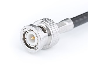
BNC connectors are very widely used in professional test and measurement and many other kinds of equipment for connecting items together and for attaching test probes. Standard BNC connectors are 50Ω but a slightly larger 75Ω version also exists. They are used in some high end monitors for component video and formerly were widely used in computer networking.
SMA
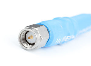
SMA is a miniature 50Ω connector, the socket having a 1/4" diameter thread. The aerials on your WiFi router may be attached with this kind of connector, and you might find it on an external aerial for a satnav.
Other ham radio and professional
There are a few other types common on professional and ham radio equipment, but which will rarely be seen in a community repair event.
Data Connectors
D Subminiature
Also known as D-sub or simply D-type, these comprise a whole family of multi-way connectors, all having a similar style D-shaped shell and 2 or 3 rows of pins. Optionally, the plug may be fitted with thumb screws to secure it to a socket. By modern standards, they are far from sub-miniature but formerly were widely used in computer equipment. Just a few may still be encountered:
- 9-pin in 2 rows: Serial port on older computers.
- 15 pin in 2 rows: Game controller port on older computers.
- 15 pin in 3 rows: Still common as a VGA video connector.
- 25 pin in 2 rows: Parallel port on older computers, or serial port on even older computers.
37 and 50 pin variant were sometimes seen at one time but practically never seen today outside a museum of computing.
Adapters and Compatibility
9 - 25 pin adapters were common in the days when both were used for serial ports. You might find one at the bottom of a box of vintage computer bits. Likewise, "gender-benders" (generally in the 25 pin format) allowing two male or two female connectors to be joined.
Centronics
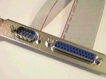
Centronics connectors were at one time familiar as the data connector on the back of a parallel interface printer. You might find a printer cable like the one illustrated (with a 25 pin D Subminiature connector on the other end) in a box of old computer bits. They came in various sizes, but the 36 pin variety was used for printers. If you wanted to resurrect an old laser printer you can get a USB to parallel interface adapter with either a Centronics or a 25 pin D subminiature connector.
RJ45
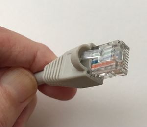
RJ45 connectors are familiar from their very widespread use on standard network cables. They have a latch which is easily broken off if you try and pull a cable out from a tangle behind a desk, but to avert this, you can get ones with a protective shield over the latch, as the one illustrated.
Network cables come in various grades, such as CAT3, good only up to 10Mbps, CAT5 which will work up to 100Mbps and CAT6 rated for 1000Mbps. Nevertheless, the connectors are all the same.
The same type of cable and connectors are used for other purposes than computer networks. For example, if you want to install a projector in a hall further away from the computer than the maximum permitted length of a VGA or HDMI cable, you can get adapters to send the video signal over standard networking cable and to recover and recondition it at the other end.
Modular Jacks
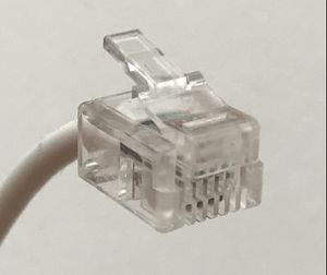
The connectors commonly known as RJ45 are in fact just one of a wider class of connectors, known as modular jacks. All are similar in construction but can have up to 10 connector positions, not all of which may be filled. RJ45 is designated 8P8C, having 8 connector positions, all of them used. 6P4C is the phone line socket in a telephone or domestic router, and the coiled lead connecting a telephone handset to the base unit often has a 4P4C connctor at each end.
To wire a modular jack, the individual wires are fed into the jack body, still insulated, and sharp points on the backs of the contacts cut through the insulation to the conductor as the jack is compressed with a special tool.
British telephone connectors
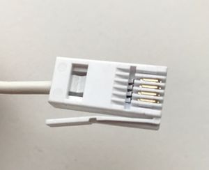
Ever since it was first permitted in the UK to purchase your own telephone and connect it to your telephone provider's master socket, phons have used a connector similar to a modular jack but with the latch on the side.
USB
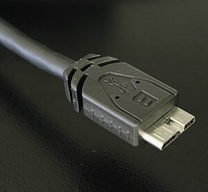
USB or Universal Seral Bus has superceded the COM and parallel ports formerly used for connecting printers, modems and scanners etc, as well as the Mini-DIN ports used for keyboards and mice. In addition it is now used (or can be) for almost all types of peripheral device.
USB devices can operate at a variety of speeds. This increases to 20Gbps for USB 3.2, using additional contacts in the connectors.
USB us also commonly used as a power or changing source for portable devices but the amount of power available is limited to 5 or 10W at 5V. (This all changes with USB-C - see later.)
Types A and B
Connectors (both male and female) come as Type A for a host device such as a laptop, and Type B for a peripheral device such as a printer. (Read on for Type C). The photo shows (from left to right):
- Micro type B plug
- Mini 8-pin Type B plug (formerly used on some Sony cameras)
- Mini Type B plug
- Type A flying lead socket
- Type A plug
- Type B plug.
Standard Type A sockets as fitted to a laptop contain a black plastic finger under the connections. Colour coding isn't mandatory nor completely standard, but generally for high speed USB 3.2 sockets, the tongue is blue, as shown in the second image. This is to be preferred for external hard disks, memory sticks and for syncing smartphones and tablets.
A yellow tongue indicates that this USB port is powered even when the laptop is shut down, and so can be used for charging, whether or not the laptop is in use.
The micro USB plug was introduced to supersede the mini version, which was perceived to have reliability problems. In fact the micro version has its own problems in that the commonly seen surface mount micro USB socket is easily pulled off the circuit board if an upward force is applied to the plug, whether through an accident or clumsiness. This can be challenging to repair, especially if the circuit traces have also lifted from the board.
USB-C
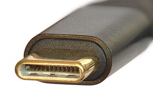
A long-standing complaint against standard USB plugs is that it always seems to take three attempts to insert them. On the first attempt, it's the right way up but mis-alligned, so you turn it over. When that doesn't work either, you turn it over again, and with a little more care the plug generally fits into the socket! USB-C plugs fix that. You can insert them either way up.
USB-C offers the same data rates as USB 3.2, but has additional power delivery capabilties. A device can request up to 100W at 20V, or if it supports Extended Power Range and with a suitable cable, up to 240W at 48V.
Adapters and Compatibility
A principle of USB is that any peripheral device will work with any USB host, though not necessarily with its greatest capability. Adapters and leads are available for all combinations of plugs and sockets.
USB is built around the concept of a host device with a Type A connector such as a computer, communicating with a peripheral device with a Type B connector such as a printer. USB OTG (On-The-Go) allows a device such as a smartphone, which normally behaves as a peripheral, to act as a host and connect to peripheral devices such as keyboards and memory sticks. An extra pin not present in full size USB connectors allows the devices to decide which role it wants to assume.
A device may optionally use its USB-C port in any of several alternate modes. The pins are then reassigned to carry analogue audio for headphones, or Thuderbolt, or for video as DisplayPort, HDMI, or MHL, and potentially other uses as well. Special adapters or cables are required.
eSATA
Anyone who has built their own desktop computer or opened one up will be familiar with the SATA cables used to connect to the disk drive. eSATA makes this into an external connection to which an external drive can be connected.
This has advantages over USB and other connection methods, being faster and slightly more efficient, and allowing additional drive capabilities such as S.M.A.R.T to be reliably accessed. A standard eSATA port doesn't supply power for the drive, but this is put right in eSATAp - a hybrid connector which will accept either a USB plug or an eSATA plug, which can then access 5V power from the USB pins.
FireWire (IEEE 1494)
Firewire, or IEEE 1594, is used for high speed data transfer, most frequently audio and video data. It is not dissimilar to USB and predates it, but has achieved far less marketshare. Unlike USB which requires one device to act as a host, FireWire adopts a peer to peer architecture in which devices cooperate amongst themselves. This allows (for example) a scanner to talk to a printer without the mediation of a computer, or a camcorder to talk equally to a computer or directly to a display.
A port provides power but this is unregulated, nominally 24 - 30V but can fall as low as 9V on battery powered devices.
FireWire appeared on Apple Mac computers in the first decade of this century but has since been superceded by Thunderbolt.
There are several versions of FireWire:
- FireWire 400 (IEEE 1394-1995) supports data rates up to 400Mbps and uses a 6 pin connector.
- IEEE 1394a-2000 is an improvement on FireWire 400, using the avaiable bandwidth more efficiently and using a 4 pin connector.
- FireWire 800 (IEEE 1394b-2002) offers a doubling of the bit rate, using a 9 pin connector.
- FireWire S1600 and S3200 use the same 9 pin connector but the only products to have been released using this standard are som Sony cameras.
A FireWire device is able to directly access the main memmory of a computer, enabling you to transfer data in bulk without the cooperation of the processor. However, this does present a security risk. Even though your unattended Windows computer might be logged out, an attacker could use the FireWire port to extract the entire contents of memory, including any private data and cryptographic keys it might find.
Adapters and Compatibility
FireWire versions are generally bckwards compatible. A "bilingual" cable can be used with both 6 and 9 pin ports.
Firewire/Tunderbolt adapters allow legacy FireWire devices to be used with the more modern Tunderbolt system. You can also get USB to FireWire adapters.
Thunderbolt
Thunderbolt was introduced in 2009 as Light Peak, originally conceived to use optical cables. It combines PCI Express and DisplayPort, and additionally provides power (though not with optical cables). Thunderbolt 1 and 2 use the same connector as Mini DisplayPort whereas Thunderbolt 3 and 4 use a USB-C connector.
Thunderbolt 1 has a data rate of 10Gbps, which is doubled in Thunderbolt 2, though Thunderbolt 1 and 2 devices are compatibe and use the same cables and connectors.
Thunderbolt 3 and 4 increase the data rate further to 40Gbps. Thunderbolt 4 additionally offers protection against the direct memory access attacks that Firewire and earliier Thunderbolt versions are susceptible to. It can also use Thunderbolt Alternate Mode USB-C hubs.
Adapters and Compatibility
Adapters are available to allow Thuderbolt 1/2 devices to be driven from a Thunderbolt 3/4 (USB-C) port, also to allow a Thunderbolt port to be connected to FireWire and HDMI devices.
Apple Lightning
Lightning is Apple's proprietary connector for connecting chargers and accessories to iPhones, iPads and iPods, superceding the 30 pin connector in 2012. It uses USB 2 but doesn't support OTG. Later devices starting in 2015 use USB 3 and can act as host, but a camera adapter is the only supported device.
Adapters and Compatibility
Lightning adapters are available for connecting headphones (in the absence of an in-built headphone port), microphones and HDMI displays. For Apple devices supporting USB 3 OTG, adapters allow the connection of cameras, memory cards and memory sticks, as well as other USB devices, subject to support by iOS.
Apple 30 pin
The Apple 30 pin connector appeard on iPhones, iPads and iPods until superceded by the much more compact Lightning connector. Each of many different functions are carried on separate pins, not all used on all devices.
Adapters and Compatibility
If you have one of those iPod docks which were popular at the time, you can get a Lightning to 30 pin adapter to use it to play music from your iPhone.
Power Connectors
Mains connectors
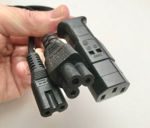
Many mains powered devices such as desktop computers, laptop power adapters, TVs and audio equipment have detachable power leads of one of three types, shown in the photo.
The figure of 8 connector is used for double-insulated devices (indicated by a symbol consisting of two squares, one inside the other). The mains plug on the other end will usually have a plastic earth pin (the larger one) and the lead is likely to be flat since it contains just two wires side by side.
Clover leaf and IEC leads are used for earthed devices. There may be no accessible metal parts to earth, but even if not there will be an earthed internal metal frame.
An IEC connector is essentially the same as a kettle lead, except that a kettle lead connector has a depression on the flat side to accommodate a ridge in the socket. This prevents an IEC lead from being used with a kettle, which would overload it, but you can if you like use a kettle lead in a device with an IEC mains inlet.
You can get adapters to allow you to use an IEC lead with a device having a clover leaf mains inlet and vice versa, and also to allow either a clover leaf or IEC lead to be used to power a device with figure of eight inlet but not the reverse, as the device would not then be earthed.
Low voltage power connectors
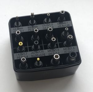
There are numerous types of low voltage power connectors used by any device with a separate mains power adaptor or charger. The photo shows a set of tips to fit on a universal lead.
The circular ones have a designation such as 5.5x2.1, indicating the external diameter of the plug, and the diameter of the central pin, both in mm.
5.5x2.1 and 5.5x2.5 are perhaps the commonest but are hard to tell apart visually. The only sure way is to try both types of plug in a given socket. A 5.5x2.5 plug will fit in a 5.5x2.1 socket, if a little loosely, but not the reverse.
Typically, the centre pin will be positive but very occasionally you might find it's negative, so always check. Sets of tips can often be connected either way to a universal lead, and universal adapters may have a polarity switch or may even be AC instead of DC! Also the voltage required by the device and supplied by the adapter may be different so check this too. Getting the polarity or the voltage wrong can destroy your gadget, so beware! Always check markings and if in doubt, check the voltage and polarity with a multimeter.
Laptop power connectors
Unfortunately there is little or no standardisation amongst laptop power connectors nor of the voltages laptops require. Most laptop power supplies produce between 18 and 20V and have a round connector.
Some manufacturers such as Dell and Lenovo use the same adapter type across a wide range of laptops, though often with divergences amongst consumer grade products. For a number of years Lenovo have used a round connector but more recently have moved to a rectangular one similar in size to a USB plug. Fortunately, adapters are available allowing you to use an old Lenovo adapter with a newer laptop (or vice versa).
Some Apple MacBooks use the MagSafe magnetically-attached power connector. There have been three variants of this: MagSafe 1, 2 and 3, each smaller than its predecessor. The idea of a magnetically attached power cable is derived from deep fryers and other cooking appliances where tripping over the power cable could result in a dangerous spill of hot liquid. The MagSafe conector similarly averts the risk of a laptop being pulled off a desk if someone trips on the power cable.
A MagSafe connector can be attached either way round. It has 5 pins, the outer pair being ground and the next pair being power. The small central pin is used for signalling, allowing the laptop to determine the power rating of the adapter and to control the LED in the connector, however, only power and ground are connected through the cable to the adapter body.
Problems with the cable insulation cracking are common and can lead to overheating and potentially a risk of fire. Particularly vulnerable are the points where the cable enters the MagSafe connector or the adapter body, and these should be protected with Sugru before the deterioration starts to affect the insulation on the two wires within the outer sheath.
USB
USB delivers power at 5V and up to 1A as standard, more in the case of USB C. Hence this is an attractive option for powering or charging a variety of devices beyond smartphones and tablets, and is becoming common on ultra-ythin laptops.
Use of Micro USB is common (Mini USB on older devices), and we can expect to see USB C increasingly as the preferred method following moves in the European Union to mandate this in order to reduce the e-waste resulting from the proliferation of chargers.
External Links
- The Hardware Book (download from The Wayback Machine) contains details of many legacy connectors such as those used on home and personal computers from the 1980's and 90's, including serial and parallel cables and adapters which you might need for an old printer, scanner or modem.
- The Electronic Connector Book (website and hard-copy book) contains an exhaustive list of hundreds of types of connector.

