Optoelectronic components: Difference between revisions
No edit summary |
|||
| Line 5: | Line 5: | ||
==Summary== | ==Summary== | ||
Of all our senses, sight is our richest source of information about the world around us. Naturally, then, this is often the best way in which electronic devices can communicate with us. This can be using simple indicator lights through to highly complex large format | Of all our senses, sight is our richest source of information about the world around us. Naturally, then, this is often the best way in which electronic devices can communicate with us. This can be using simple indicator lights through to highly complex large format display screens, and can embody several different technologies. Conversely, our gadgets often need to detect light, whether just to sense when a beam has been interrupted for example by closing a lid, or in order to image a scene as in a camera. Again, several principles are used across different devices. | ||
In total, this amounts to a fair number of different types of component, but it's generally easy to identify them, to understand what they're supposed to be doing, and whether they are indeed doing it. | In total, this amounts to a fair number of different types of component, but it's generally easy to identify them, to understand what they're supposed to be doing, and whether they are indeed doing it. | ||
| Line 19: | Line 19: | ||
Battery operated torches and bicycle lights once exclusively used small low voltage filament bulbs with a screw base and somewhat larger 12V versions were used in cars. | Battery operated torches and bicycle lights once exclusively used small low voltage filament bulbs with a screw base and somewhat larger 12V versions were used in cars. | ||
You may still sometimes come across small low voltage filament bulbs, either with a screw base, or wire-ended and only a few | You may still sometimes come across small low voltage filament bulbs, either with a screw base, or wire-ended and only a few millimetres in diameter illuminating the dial in an older radio or alarm clock. Until displaced by LEDs, they were extremely commonly used as Christmas tree lights with many low voltage bulbs in [[Glossary:Series|series]] adding up to the mains voltage of 240V. | ||
===Neon bulbs=== | ===Neon bulbs=== | ||
[[File:AC powered NE-2 type neon lamp close-up.jpg|thumb|150px|right|A neon lamp. Both electrodes are glowing since it is being operated from AC.]] | [[File:AC powered NE-2 type neon lamp close-up.jpg|thumb|150px|right|A neon lamp. Both electrodes are glowing since it is being operated from AC.]] | ||
Before LEDs became cheap and common, a neon bulb would very often be used as a power-on indicator. A common form consists of two electrodes sealed inside a 5mm glass tube containing a trace of neon gas. When lit, it gives a gently orange glow. Other | Before LEDs became cheap and common, a neon bulb would very often be used as a power-on indicator. A common form consists of two electrodes sealed inside a 5mm glass tube containing a trace of neon gas. When lit, it gives a gently orange glow. Other colours are sometimes seen, in particular green. These either use a different gas which naturally glows green, or a gas producing blue and ultraviolet with a phosphor coating inside the glass which glows with the required colour. | ||
Neon bulbs may require over 100V in order to light, but then operate at a voltage of around 30% less. With the added fact that they work equally with [[Glossary:AC|AC]] or [[Glossary:DC|DC]], they are very easy to operate from the mains. All you need is a 1MΩ resistor in series to limit the current. On no account must this be omitted! | Neon bulbs may require over 100V in order to light, but then operate at a voltage of around 30% less. With the added fact that they work equally with [[Glossary:AC|AC]] or [[Glossary:DC|DC]], they are very easy to operate from the mains. All you need is a 1MΩ resistor in series to limit the current. On no account must this be omitted! | ||
| Line 33: | Line 33: | ||
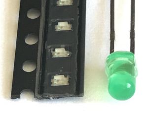
LEDs come in many different forms. As electronic components, the 3 or 5mm clear or coloured packages are most familiar but other shapes and sizes are available. Sometimes these contain 2 or 3 LED chips emitting different colours and with up to 4 wires, allowing different colours to be produced. Much smaller surface mount LEDs are often found on circuit boards adjacent to a lens or light pipe allowing their glow to be seen on the outside of an appliance. | LEDs come in many different forms. As electronic components, the 3 or 5mm clear or coloured packages are most familiar but other shapes and sizes are available. Sometimes these contain 2 or 3 LED chips emitting different colours and with up to 4 wires, allowing different colours to be produced. Much smaller surface mount LEDs are often found on circuit boards adjacent to a lens or light pipe allowing their glow to be seen on the outside of an appliance. | ||
In COB (or Chip On Board LEDS), several or many blue LED chips are mounted directly on a | In COB (or Chip On Board LEDS), several or many blue LED chips are mounted directly on a circuit board and covered with a phosphor which converts the blue to white light. In "filament" LED light bulbs the LED chips are mounted on a thin flexible strip, sometimes bent into a helix or other shape for aesthetic effect. | ||
===Lasers diodes=== | ===Lasers diodes=== | ||
[[File:Diode laser.jpg|thumb|right|A diode laser.]] | [[File:Diode laser.jpg|thumb|right|A diode laser.]] | ||
There are many types of laser but their defining property is that they produce light in which all the light waves are lined up perfectly into a single beam. Think of the single continuous tone produced by an organ pipe as opposed by the hissing sound of an escape of high | There are many types of laser but their defining property is that they produce light in which all the light waves are lined up perfectly into a single beam. Think of the single continuous tone produced by an organ pipe as opposed by the hissing sound of an escape of high pressure air. | ||
An LED can be specially constructed so that much of the light bounces back and forth between two reflecting surfaces like sound in an organ pipe. Fed with a sufficiently large current, this can produce laser light instead of the disorganised light that a LED normally produces as electrons pass randomly through it. | An LED can be specially constructed so that much of the light bounces back and forth between two reflecting surfaces like sound in an organ pipe. Fed with a sufficiently large current, this can produce laser light instead of the disorganised light that a LED normally produces as electrons pass randomly through it. | ||
| Line 51: | Line 51: | ||
A junction transistor consists essentially of two diodes in close proximity such that a small current passing through one allows a much larger current to flow through the other. Exposed to light, this is equivalent to a photodiode connected to a transistor to amplify the photodiode's current. | A junction transistor consists essentially of two diodes in close proximity such that a small current passing through one allows a much larger current to flow through the other. Exposed to light, this is equivalent to a photodiode connected to a transistor to amplify the photodiode's current. | ||
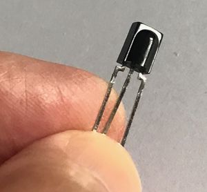
Two transistors can be connected in a "[[wikipedia:Darlington_transistor|Darlington pair]]" in which the second transistor further amplifies the current from the first. If the first is a photo-transistor the result is a darlington photo-transistor with still greater sensitivity. When designed to receive the signal | Two transistors can be connected in a "[[wikipedia:Darlington_transistor|Darlington pair]]" in which the second transistor further amplifies the current from the first. If the first is a photo-transistor the result is a darlington photo-transistor with still greater sensitivity. When designed to receive the signal from an infrared remote there may be additional circuitry integrated with the photo-transistor in order to shape and conditional the signal ready for decoding. | ||
===Light-dependant resistors (LDRs)=== | ===Light-dependant resistors (LDRs)=== | ||
| Line 57: | Line 57: | ||
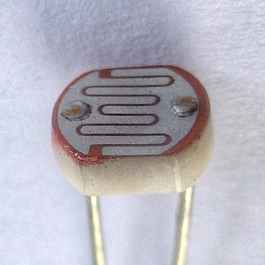
A Light Dependant or Photo Resistor uses a semiconductor such as cadmium sulphide which, in the dark, has few electrons free to carry a current and so has a high resistance. If you shine a light on it, more electrons are released and so its resistance is reduced. Unlike a photodiode, it's a pure resistance, conducting equally in either direction. | A Light Dependant or Photo Resistor uses a semiconductor such as cadmium sulphide which, in the dark, has few electrons free to carry a current and so has a high resistance. If you shine a light on it, more electrons are released and so its resistance is reduced. Unlike a photodiode, it's a pure resistance, conducting equally in either direction. | ||
The use of cadmium is now restricted on account of its toxicity and so LDRs are most likely to be found in older equipment. They were frequently used in photographic light meters, to control street lights, night lights and the brightness of a digital clock with a LED-based 7-segment display. They have also been used in musical equipment. Some kind of vane actuated by a foot pedal controls the amount of light from a lamp falling on an LDR, which in turn controls the volume or other characteristic of the music. This avoids any crackling that a [[Glossary:Potentiometer|potentiometer]] used for this | The use of cadmium is now restricted on account of its toxicity and so LDRs are most likely to be found in older equipment. They were frequently used in photographic light meters, to control street lights, night lights and the brightness of a digital clock with a LED-based 7-segment display. They have also been used in musical equipment. Some kind of vane actuated by a foot pedal controls the amount of light from a lamp falling on an LDR, which in turn controls the volume or other characteristic of the music. This avoids any crackling that a [[Glossary:Potentiometer|potentiometer]] used for this purpose might produce after heavy use. | ||
===PIR detectors=== | ===PIR detectors=== | ||
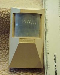
| Line 65: | Line 65: | ||
==Optical sensors== | ==Optical sensors== | ||
[[File:Reflective infrared sensor.jpg|thumb|right|A reflective infrared sensor. ]] | [[File:Reflective infrared sensor.jpg|thumb|right|A reflective infrared sensor. ]] | ||
Optical sensors are often used to detect a mechanical condition, such | Optical sensors are often used to detect a mechanical condition, such as a lid being closed, a finger guard in place, a moving part being at the limit of its travel or the motion of a wheel. This can be done with a LED and a light detector such as a photodiode, phototransistor or photo Darlington, but for convenience, the two are often packaged together. Very often an infrared LED is used since photodiodes and their cousins have good sensitivity in the infrared. | ||
There are two types. In the reflective type the LED and light detector face the same way in order to detect a reflective surface in front of them. In a transmissive one, they face each other across a gap. These are very common in older mechanical mice, in which a wheel with slots in it is placed in the gap in order to sense its rotation as the mouse moves. | There are two types. In the reflective type the LED and light detector face the same way in order to detect a reflective surface in front of them. In a transmissive one, they face each other across a gap. These are very common in older mechanical mice, in which a wheel with slots in it is placed in the gap in order to sense its rotation as the mouse moves. | ||
| Line 83: | Line 83: | ||
==Image sensors== | ==Image sensors== | ||
[[File:Ccd-sensor.jpg|thumb|right|An image | [[File:Ccd-sensor.jpg|thumb|right|An image sensor on a flexible circuit board.]] | ||
Until semiconductor image sensors started to appear in the 1990's, all TV and video cameras used vacuum tubes to capture images. Like an old fashioned [[Glossary:CRT|CRT]] (used in TVs before flat screens became available), these used a scanning electron beam to read out the brightness of the image at each point. There were various different types of [[wikipedia:Video_camera_tube|video camera tube]] but you are never likely to see any of them today outside a museum. | Until semiconductor image sensors started to appear in the 1990's, all TV and video cameras used vacuum tubes to capture images. Like an old fashioned [[Glossary:CRT|CRT]] (used in TVs before flat screens became available), these used a scanning electron beam to read out the brightness of the image at each point. There were various different types of [[wikipedia:Video_camera_tube|video camera tube]] but you are never likely to see any of them today outside a museum. | ||
All image sensors today consist | All image sensors today consist essentially of a large array of photodiodes fabricated on a single silicon chip. A colour image sensor will have separate photodiodes for each of the three primary colours. There are two types: | ||
* In CMOS sensors the pixels are read out by row and column in the same | * In CMOS sensors the pixels are read out by row and column in the same way as the pixels are addressed in a flat screen display. These are the cheaper sort and use the least power and hence are used in the majority of still cameras and webcams. | ||
* CCD or Charge Coupled Devices read out the data by passing a charge from each pixel along its row (or column) to the end, like a [[wikipedia:Bucket-brigade_device|bucket brigade]]. This requires less circuitry per pixel for the readout and hence allows more area for collecting light, and so is used in high end cameras. | * CCD or Charge Coupled Devices read out the data by passing a charge from each pixel along its row (or column) to the end, like a [[wikipedia:Bucket-brigade_device|bucket brigade]]. This requires less circuitry per pixel for the readout and hence allows more area for collecting light, and so is used in high end cameras. | ||
| Line 94: | Line 94: | ||
* 7-segment displays are very familiar as calculator displays. Each digit is formed by a unique combination of the 7 segments. 9 segments have sometimes been used. | * 7-segment displays are very familiar as calculator displays. Each digit is formed by a unique combination of the 7 segments. 9 segments have sometimes been used. | ||
* 14- and 16-segment displays allow alphanumeric data to be represented in a similar way. These and 7 segment displays may additionally include a decimal point. | * 14- and 16-segment displays allow alphanumeric data to be represented in a similar way. These and 7 segment displays may additionally include a decimal point. | ||
* Dot | * Dot matrix displays represent data graphically, ranging from simple devices representing a single line of alphanumeric characters by an 8x5 matrix of dots per character, up to high-end TV and computer screens with many millions of pixels. | ||
Of the many different technologies, some are of largely historical interest. The more current technologies are treated first. | Of the many different technologies, some are of largely historical interest. The more current technologies are treated first. | ||
===LCD=== | ===LCD=== | ||
[[File:Casio W-59 digital watch.jpg|thumb|right|A digital | [[File:Casio W-59 digital watch.jpg|thumb|right|A digital watch with LCD display]] | ||
LCDs (or liquid crystal displays) depend on [[wikipedia:Polarization_(physics)|polarisation]] of light. Between two polarising filters, a special liquid rotates the plan of polarisation of the light passing through if subject to an electric field.Hence light can pass though only if the plane of polarisation is aligned with both filters. | LCDs (or liquid crystal displays) depend on [[wikipedia:Polarization_(physics)|polarisation]] of light. Between two polarising filters, a special liquid rotates the plan of polarisation of the light passing through if subject to an electric field. Hence light can pass though only if the plane of polarisation is aligned with both filters. | ||
Very often, as in a calculator display, the LCD is configured to be view from the front. With a | Very often, as in a calculator display, the LCD is configured to be view from the front. With a single polarising filter and a reflective layer at the back, a segment appears dark if the polarisation of light is twisted and hence unable to pass through the filter on its way out again. Other LCD displays have a back-light to allow them to be read in poor light. Laptop and LCD TV screens have a large back-light, and LCD projectors focus the light from a bulb through the LCD. Colour displays have separate LCD pixels for the three colours, each with a coloured filter. | ||
LCDs are activated by an electric field and don't | LCDs are activated by an electric field and don't require any current to flow through them. As a result, simple LCD displays are well suited to low power battery devices such as calculators ad digital clocks and watches. | ||
===LED=== | ===LED=== | ||
| Line 111: | Line 111: | ||
===OLED=== | ===OLED=== | ||
Normal LEDs use a | Normal LEDs use a crystalline semiconductor material but certain organic materials can be made to emit light in the same way, albeit with lower efficiency. The principle of operation is not quite the same, but unfortunately a knowledge of quantum mechanics is required to understand the difference. | ||
[[File:E-ink and OLED displays.jpg|thumb|right|E-ink (left) and OLED (right) displays compared.]] | [[File:E-ink and OLED displays.jpg|thumb|right|E-ink (left) and OLED (right) displays compared.]] | ||
| Line 119: | Line 119: | ||
E-ink displays are familiar as the screens of many e-book readers. They have the advntage that once an image has been written to the display, no power is required to maintain it. Nevertheless, it may fade over period of months or more. | E-ink displays are familiar as the screens of many e-book readers. They have the advntage that once an image has been written to the display, no power is required to maintain it. Nevertheless, it may fade over period of months or more. | ||
The display contains oil with a black dye in which are suspended tiny white particles. These can be attracted to the front to show a white pixel by a voltage applied between | The display contains oil with a black dye in which are suspended tiny white particles. These can be attracted to the front to show a white pixel by a voltage applied between electrodes on the front and back of the display. Being purely reflective, the display can be read in bright light which would make any display hard to read which emits its own light. A disadvantage is that the display is slow to respond so not generally suitable for moving images. | ||
In addition to relatively large e-ink displays, smaller ones are available, some capable of displayig three colours such as black, white and red - useful | In addition to relatively large e-ink displays, smaller ones are available, some capable of displayig three colours such as black, white and red - useful for indicating a warning. | ||
===DMD=== | ===DMD=== | ||
A DMD or Digital Micromirror Device is often used as an alternative to a LCD in a data projector. It consists of a large number of tiny mirrors, one for each pixel, fabricated on a silicon chip. Each mirror can be | A DMD or Digital Micromirror Device is often used as an alternative to a LCD in a data projector. It consists of a large number of tiny mirrors, one for each pixel, fabricated on a silicon chip. Each mirror can be individually deflected electrically so as to reflect the light from the lamp either through the projection lens and onto the screen, or into a light sink, where it's absorbed. The brightness of each pixel is controlled by switching it on and off very rapidly, the "on" proportion of the time corresponding to the brightness required. A colour display is achieved by illuminating it with red, green and blue light in turn through a spinning colour wheel with three colour filters. | ||
A projector using a DMD is immediately recognisable. If you scan your eye rapidly across the screen you will see the red, blue and green images separating. | A projector using a DMD is immediately recognisable. If you scan your eye rapidly across the screen you will see the red, blue and green images separating. | ||
===Plasma=== | ===Plasma=== | ||
[[File:Plasma-display-composition.svg|thumb|right|Construction | [[File:Plasma-display-composition.svg|thumb|right|Construction of a plasma display.]] | ||
Plasma displays are largely obsolete, having been overtaken by LCD and OLED displays as these have improved, largely eliminating their advantage of high contrast. | Plasma displays are largely obsolete, having been overtaken by LCD and OLED displays as these have improved, largely eliminating their advantage of high contrast. | ||
| Line 139: | Line 139: | ||
[[File:Vacuum fluorescent 1.jpg|thumb|right|A vacuum fluorescent display.]] | [[File:Vacuum fluorescent 1.jpg|thumb|right|A vacuum fluorescent display.]] | ||
A derivative technology was later used in vacuum fluorescent displays, generally | A derivative technology was later used in vacuum fluorescent displays, generally configured as 7 or 15 segment displays with individual segments turned on or off by control electrodes. Additional individually illuminated status indicators were often included. This kind of display was very commonly found in videocassette recorders and microwave ovens for a good many years until displaced by LCD or LED displays. | ||
===CRTs=== | ===CRTs=== | ||
[[File:Cathode_ray_Tube.PNG|thumb|right]] | [[File:Cathode_ray_Tube.PNG|thumb|right]] | ||
A discussion of display devices would hardly be complete | A discussion of display devices would hardly be complete without a mention of CRTs or Cathode Ray Tubes, once ubiquitous in TVs and computer monitors though now completely obsoleted by flat screen displays. | ||
A beam of electrons is fired from a electron gun towards a phosphor-coated screen. The beam is deflected horizontally and vertically by the magnetic fields produced by coils of wire arranged around the next of the tube. Smaller CRTs used in test and scientific equipment instead use two pairs of plates inside the tube, one pair above and below and the other either side of the electron beam. Voltages applied to these plates deflect it in the same way. This uses much less power but the possible angle of deflection is less and hence the tube has to be considerably longer in proportion to the screen size. | A beam of electrons is fired from a electron gun towards a phosphor-coated screen. The beam is deflected horizontally and vertically by the magnetic fields produced by coils of wire arranged around the next of the tube. Smaller CRTs used in test and scientific equipment instead use two pairs of plates inside the tube, one pair above and below and the other either side of the electron beam. Voltages applied to these plates deflect it in the same way. This uses much less power but the possible angle of deflection is less and hence the tube has to be considerably longer in proportion to the screen size. | ||
Colour CRTs had three electron guns and a "shadow mask" immediately behind the screen. The electron beams from the three guns passed | Colour CRTs had three electron guns and a "shadow mask" immediately behind the screen. The electron beams from the three guns passed through holes in the shadow mask at slightly different angles, so striking red, green or blue phosphor spots. | ||
===Nixie tubes=== | ===Nixie tubes=== | ||
| Line 153: | Line 153: | ||
Nixie tubes were a early form of numeric display operating on the principle of a neon lamp. Ten electrodes, each shaped in the form of a digit, could be energised, one at a time, causing them to glow with the characteristic orange neon glow. | Nixie tubes were a early form of numeric display operating on the principle of a neon lamp. Ten electrodes, each shaped in the form of a digit, could be energised, one at a time, causing them to glow with the characteristic orange neon glow. | ||
They have been completely | They have been completely superseded for commercial use by several of the technologies already mentioned, all less bulky and using voltages more easily interfaced to modern digital electronics, yet they retain a certain aesthetic appeal and remain popular in the maker community. | ||
===Dekatrons=== | ===Dekatrons=== | ||
[[File:Dekatron.gif|thumb|right]] | [[File:Dekatron.gif|thumb|right]] | ||
Dekatrons were another neon-based display with built-in counting ability. In a ring of 30 electrodes, one in every three was | Dekatrons were another neon-based display with built-in counting ability. In a ring of 30 electrodes, one in every three was permanently energised and the neon discharge would sit on just one of them, reducing the voltage on all ten to below that required to initiate a discharge on any of the other nine. Of the remaining 20 electrodes, the 10 just clockwise from a main electrode were connected together as were all the electrodes just anticlockwise. | ||
A pulse applied to the electrodes just clockwise from the main electrodes followed by a pulse to the electrodes just anticlockwise would cause the discharge to jump to each of those in turn before settling on the next main electrode. | A pulse applied to the electrodes just clockwise from the main electrodes followed by a pulse to the electrodes just anticlockwise would cause the discharge to jump to each of those in turn before settling on the next main electrode. | ||
Dekatrons were frequently used in the 1950's and 60's in electronic test equipment such as counters and timers and | Dekatrons were frequently used in the 1950's and 60's in electronic test equipment such as counters and timers and occasionally were used to construct computers. The [https://www.bbc.co.uk/news/technology-20395212 Harwell Dekatron Computer] contained 828 dekatrons and is now on display as the oldest fully working computer in the world at the [https://www.tnmoc.org/first-generation-gallery NationalMuseum of Computing] at Bletchley Park. | ||
==And now ...== | ==And now ...== | ||
Revision as of 10:25, 3 June 2023
This page covers components which emit or detect light, or change their appearance under the control of an electrical input: how to recognise them and understand how thy might fail.
Summary
Of all our senses, sight is our richest source of information about the world around us. Naturally, then, this is often the best way in which electronic devices can communicate with us. This can be using simple indicator lights through to highly complex large format display screens, and can embody several different technologies. Conversely, our gadgets often need to detect light, whether just to sense when a beam has been interrupted for example by closing a lid, or in order to image a scene as in a camera. Again, several principles are used across different devices.
In total, this amounts to a fair number of different types of component, but it's generally easy to identify them, to understand what they're supposed to be doing, and whether they are indeed doing it.
Emitters of light
Filament lamps
Filament bulbs consist of a very fine coiled tungsten wire which glows white hot when a current is passed through it. A glass envelope containing an inert gas protects it from very quickly burning out. Filament bulbs are very inefficient and so can no longer be sold for domestic lighting.
Quartz halogen bulbs are similar but have a fused silica envelope which contains a small quantity of a halogen gas. This combines with the tungsten as it gradually evaporates from the filament, and decomposes when it comes into contact with the hot filament, depositing the tungsten back on it. As a result, the filament can be run significantly hotter without shortening its life, increasing its efficiency and producing a whiter light. Even so, the efficiency is not great. Often, the silica envelope is itself enclosed in a glass bulb as it can become very hot.
Battery operated torches and bicycle lights once exclusively used small low voltage filament bulbs with a screw base and somewhat larger 12V versions were used in cars.
You may still sometimes come across small low voltage filament bulbs, either with a screw base, or wire-ended and only a few millimetres in diameter illuminating the dial in an older radio or alarm clock. Until displaced by LEDs, they were extremely commonly used as Christmas tree lights with many low voltage bulbs in series adding up to the mains voltage of 240V.
Neon bulbs
Before LEDs became cheap and common, a neon bulb would very often be used as a power-on indicator. A common form consists of two electrodes sealed inside a 5mm glass tube containing a trace of neon gas. When lit, it gives a gently orange glow. Other colours are sometimes seen, in particular green. These either use a different gas which naturally glows green, or a gas producing blue and ultraviolet with a phosphor coating inside the glass which glows with the required colour.
Neon bulbs may require over 100V in order to light, but then operate at a voltage of around 30% less. With the added fact that they work equally with AC or DC, they are very easy to operate from the mains. All you need is a 1MΩ resistor in series to limit the current. On no account must this be omitted!
LEDs
LEDs or Light Emitting Diodes have become ubiquitous since they first appeared in the 1970's. For many years only infrared, red and green were available, with the first practical blue LEDs appearing only in the 1990's, followed by violet and ultraviolet. LEDs are essentially no different from other semiconductor diodes except that instead of (most often) silicon, they use semiconductor materials with particular quantum mechanical properties causing the energy lost by electrons passing through them in a forward direction to be released as photons of light rather than as heat.
LEDs come in many different forms. As electronic components, the 3 or 5mm clear or coloured packages are most familiar but other shapes and sizes are available. Sometimes these contain 2 or 3 LED chips emitting different colours and with up to 4 wires, allowing different colours to be produced. Much smaller surface mount LEDs are often found on circuit boards adjacent to a lens or light pipe allowing their glow to be seen on the outside of an appliance.
In COB (or Chip On Board LEDS), several or many blue LED chips are mounted directly on a circuit board and covered with a phosphor which converts the blue to white light. In "filament" LED light bulbs the LED chips are mounted on a thin flexible strip, sometimes bent into a helix or other shape for aesthetic effect.
Lasers diodes
There are many types of laser but their defining property is that they produce light in which all the light waves are lined up perfectly into a single beam. Think of the single continuous tone produced by an organ pipe as opposed by the hissing sound of an escape of high pressure air.
An LED can be specially constructed so that much of the light bounces back and forth between two reflecting surfaces like sound in an organ pipe. Fed with a sufficiently large current, this can produce laser light instead of the disorganised light that a LED normally produces as electrons pass randomly through it.
The current through a laser diode has to be controlled within fairly precise limits. Not enough and it simply won't "lase", too much and it will be destroyed by the heat generated. Consequently a laser diode is normally housed in a metal can with a glass window allowing the heat to be carried away and the light to escape, and also containing a photodiode (see later) to monitor the light output. This allows the controlling circuitry to supply sufficient current but not too much.
Light detectors
Photo-diodes and photo-transistors
A diode only conducts in one direction, but in the reverse direction, if you shine a light on it the light will release electrons, enabling a small current to flow. Most diodes come in an opaque housing, or else the light-sensitive region is so small that the effect is minimal, but a photodiode by contrast is constructed so as to maximise the effect.
A junction transistor consists essentially of two diodes in close proximity such that a small current passing through one allows a much larger current to flow through the other. Exposed to light, this is equivalent to a photodiode connected to a transistor to amplify the photodiode's current.
Two transistors can be connected in a "Darlington pair" in which the second transistor further amplifies the current from the first. If the first is a photo-transistor the result is a darlington photo-transistor with still greater sensitivity. When designed to receive the signal from an infrared remote there may be additional circuitry integrated with the photo-transistor in order to shape and conditional the signal ready for decoding.
Light-dependant resistors (LDRs)
A Light Dependant or Photo Resistor uses a semiconductor such as cadmium sulphide which, in the dark, has few electrons free to carry a current and so has a high resistance. If you shine a light on it, more electrons are released and so its resistance is reduced. Unlike a photodiode, it's a pure resistance, conducting equally in either direction.
The use of cadmium is now restricted on account of its toxicity and so LDRs are most likely to be found in older equipment. They were frequently used in photographic light meters, to control street lights, night lights and the brightness of a digital clock with a LED-based 7-segment display. They have also been used in musical equipment. Some kind of vane actuated by a foot pedal controls the amount of light from a lamp falling on an LDR, which in turn controls the volume or other characteristic of the music. This avoids any crackling that a potentiometer used for this purpose might produce after heavy use.
PIR detectors
Passive Infra-Red or PIR detectors work on a principle related to the piezoelectric effect, in which a strain applied to certain types of crystal slightly displaces the positive and negative charges within it, creating a net voltage across opposite faces. In the pyroelectric effect, this strain is produced by the very slight warming produced by infrared (heat) radiation. In a PIR detector, a number of plastic lenses formed i a single piece of transparent plastic are placed in front of a pyroelectric sensor causing multiple images of a warm body (a person, an animal or a vehicle) to move across the sensor as it moves across the field of view. In fact there may be two sensors with the detector designed to detect differences between their outputs, reducing false detections which might be caused by environmental or electrical effects affecting both equally.
Optical sensors
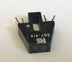
Optical sensors are often used to detect a mechanical condition, such as a lid being closed, a finger guard in place, a moving part being at the limit of its travel or the motion of a wheel. This can be done with a LED and a light detector such as a photodiode, phototransistor or photo Darlington, but for convenience, the two are often packaged together. Very often an infrared LED is used since photodiodes and their cousins have good sensitivity in the infrared.
There are two types. In the reflective type the LED and light detector face the same way in order to detect a reflective surface in front of them. In a transmissive one, they face each other across a gap. These are very common in older mechanical mice, in which a wheel with slots in it is placed in the gap in order to sense its rotation as the mouse moves.
There are other types of optical sensor for more specialised purposes, for example three light sensors covered by three different coloured filters can be used to determine a colour, or the colour temperature of alight source or a scene.
Opto isolators
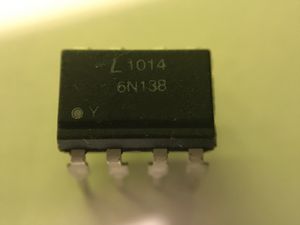
Sometimes it's necessary to electrically isolate one part of a circuit from another. This is easily done, as in an optical sensor, with a LED and a photo detector mounted in a single package. As with an optical sensor, the photo detector can be a phototransistor or photo darlington, or if the intention is to isolate a purely digital (on/off) signal, there may be additional circuitry included to further condition the output. That might even include a triac capable of directly switching AC mains. You then have a solid state relay allowing a mains circuit to be switched on and off by an electrically isolated low voltage timer or other device.
Opto isolators commonly come as a 6 or 8 pin dual-inline package just like a simple IC.
Opto isolators are extremely common in switch mode power supplies. Isolation of the output power from the mains input is achieved with a transformer but feedback is required from the output to the input in order to regulate the power so as to produce a constant output voltage. If you look inside such a power supply you will find the transformer and an opto isolator both straddling a very clear demarcation on the board (often a physical slot) between all the circuitry directly fed from the mains and all the circuity feeding the output.
Musical instruments with a MIDI interface (allowing them to be connected to MIDI synthesisers, sequencers and other instruments) always contain an opto isolator on the MIDI input, as required by the MIDI interface specification. This eliminates the risk of ground loops - spurious currents flowing between different pieces of equipment, each with its own mains power supply.
Image sensors
Until semiconductor image sensors started to appear in the 1990's, all TV and video cameras used vacuum tubes to capture images. Like an old fashioned CRT (used in TVs before flat screens became available), these used a scanning electron beam to read out the brightness of the image at each point. There were various different types of video camera tube but you are never likely to see any of them today outside a museum.
All image sensors today consist essentially of a large array of photodiodes fabricated on a single silicon chip. A colour image sensor will have separate photodiodes for each of the three primary colours. There are two types:
- In CMOS sensors the pixels are read out by row and column in the same way as the pixels are addressed in a flat screen display. These are the cheaper sort and use the least power and hence are used in the majority of still cameras and webcams.
- CCD or Charge Coupled Devices read out the data by passing a charge from each pixel along its row (or column) to the end, like a bucket brigade. This requires less circuitry per pixel for the readout and hence allows more area for collecting light, and so is used in high end cameras.
Displays
Whatever technology they use, displays can be made in several different formats of increasing complexity.
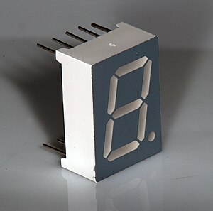
- 7-segment displays are very familiar as calculator displays. Each digit is formed by a unique combination of the 7 segments. 9 segments have sometimes been used.
- 14- and 16-segment displays allow alphanumeric data to be represented in a similar way. These and 7 segment displays may additionally include a decimal point.
- Dot matrix displays represent data graphically, ranging from simple devices representing a single line of alphanumeric characters by an 8x5 matrix of dots per character, up to high-end TV and computer screens with many millions of pixels.
Of the many different technologies, some are of largely historical interest. The more current technologies are treated first.
LCD
LCDs (or liquid crystal displays) depend on polarisation of light. Between two polarising filters, a special liquid rotates the plan of polarisation of the light passing through if subject to an electric field. Hence light can pass though only if the plane of polarisation is aligned with both filters.
Very often, as in a calculator display, the LCD is configured to be view from the front. With a single polarising filter and a reflective layer at the back, a segment appears dark if the polarisation of light is twisted and hence unable to pass through the filter on its way out again. Other LCD displays have a back-light to allow them to be read in poor light. Laptop and LCD TV screens have a large back-light, and LCD projectors focus the light from a bulb through the LCD. Colour displays have separate LCD pixels for the three colours, each with a coloured filter.
LCDs are activated by an electric field and don't require any current to flow through them. As a result, simple LCD displays are well suited to low power battery devices such as calculators ad digital clocks and watches.
LED
Early pocket calculators used 7 segment displays using LEDs to illuminate the segments with a lens over each digit to magnify it. The current drawn by these resulted in a short battery life. Larger 7 segment displays are found in some digital clocks. These often consist of individual packages each displaying a single digit. Similar packages each containing an 8x8 matrix of LEDs can be stacked together to display text. Larger displays consisting of hundreds up to many thousands of individual LEDs are often used for signage in transport and retail settings, and very large ones using tri-colour LEDs are used to display full motion video as advertising hoardings.
OLED
Normal LEDs use a crystalline semiconductor material but certain organic materials can be made to emit light in the same way, albeit with lower efficiency. The principle of operation is not quite the same, but unfortunately a knowledge of quantum mechanics is required to understand the difference.
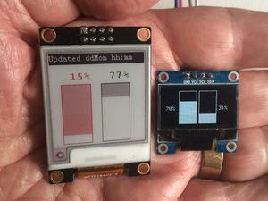
OLED displays consist of a matrix of pixels. They range from very small devices with just a few hundred pixels, often blue-ish white, up to large format TV screens. Unlike LCD displays, they need no back light and so can be made thinner and produce higher contrast levels. OLED displays have a limited life though this has been improved as the technology has been refined.
E-ink
E-ink displays are familiar as the screens of many e-book readers. They have the advntage that once an image has been written to the display, no power is required to maintain it. Nevertheless, it may fade over period of months or more.
The display contains oil with a black dye in which are suspended tiny white particles. These can be attracted to the front to show a white pixel by a voltage applied between electrodes on the front and back of the display. Being purely reflective, the display can be read in bright light which would make any display hard to read which emits its own light. A disadvantage is that the display is slow to respond so not generally suitable for moving images.
In addition to relatively large e-ink displays, smaller ones are available, some capable of displayig three colours such as black, white and red - useful for indicating a warning.
DMD
A DMD or Digital Micromirror Device is often used as an alternative to a LCD in a data projector. It consists of a large number of tiny mirrors, one for each pixel, fabricated on a silicon chip. Each mirror can be individually deflected electrically so as to reflect the light from the lamp either through the projection lens and onto the screen, or into a light sink, where it's absorbed. The brightness of each pixel is controlled by switching it on and off very rapidly, the "on" proportion of the time corresponding to the brightness required. A colour display is achieved by illuminating it with red, green and blue light in turn through a spinning colour wheel with three colour filters.
A projector using a DMD is immediately recognisable. If you scan your eye rapidly across the screen you will see the red, blue and green images separating.
Plasma
Plasma displays are largely obsolete, having been overtaken by LCD and OLED displays as these have improved, largely eliminating their advantage of high contrast.
Plasma displays were the first technology enabling large screen TVs to be produced. Each pixel consisted of a tiny gas-filled cell which could be ionised by a high voltage. This caused a tiny quantity of mercury vapour to emit ultraviolet light which was converted to red, green of blue light by a phosphor.
Vacuum fluorescent
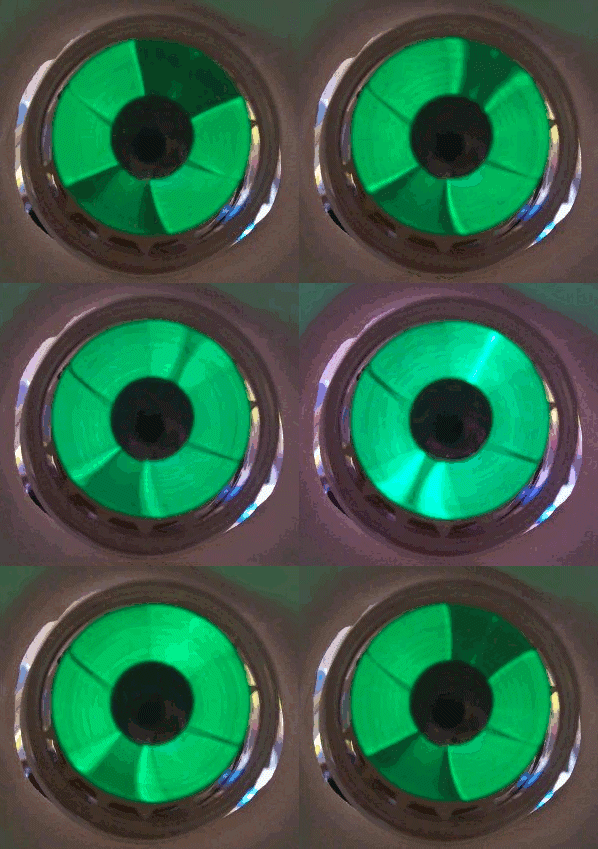
In the 1950's and 60's, FM radios using valves often had a "magic eye" tuning indicator. This was a valve in which the electrons struck a fluorescent screen causing it to glow. A voltage applied to a control electrode deviated the electron stream causing the proportion of the screen illuminated to depend on the control voltage.
A derivative technology was later used in vacuum fluorescent displays, generally configured as 7 or 15 segment displays with individual segments turned on or off by control electrodes. Additional individually illuminated status indicators were often included. This kind of display was very commonly found in videocassette recorders and microwave ovens for a good many years until displaced by LCD or LED displays.
CRTs
A discussion of display devices would hardly be complete without a mention of CRTs or Cathode Ray Tubes, once ubiquitous in TVs and computer monitors though now completely obsoleted by flat screen displays.
A beam of electrons is fired from a electron gun towards a phosphor-coated screen. The beam is deflected horizontally and vertically by the magnetic fields produced by coils of wire arranged around the next of the tube. Smaller CRTs used in test and scientific equipment instead use two pairs of plates inside the tube, one pair above and below and the other either side of the electron beam. Voltages applied to these plates deflect it in the same way. This uses much less power but the possible angle of deflection is less and hence the tube has to be considerably longer in proportion to the screen size.
Colour CRTs had three electron guns and a "shadow mask" immediately behind the screen. The electron beams from the three guns passed through holes in the shadow mask at slightly different angles, so striking red, green or blue phosphor spots.
Nixie tubes
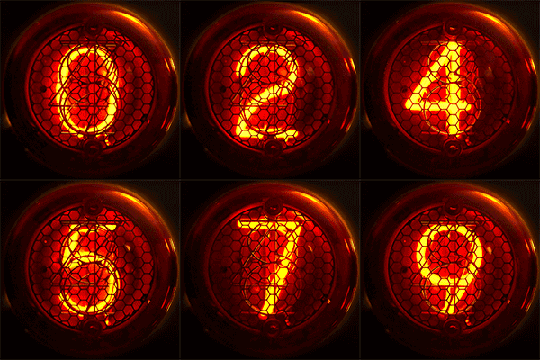
Nixie tubes were a early form of numeric display operating on the principle of a neon lamp. Ten electrodes, each shaped in the form of a digit, could be energised, one at a time, causing them to glow with the characteristic orange neon glow.
They have been completely superseded for commercial use by several of the technologies already mentioned, all less bulky and using voltages more easily interfaced to modern digital electronics, yet they retain a certain aesthetic appeal and remain popular in the maker community.
Dekatrons
Dekatrons were another neon-based display with built-in counting ability. In a ring of 30 electrodes, one in every three was permanently energised and the neon discharge would sit on just one of them, reducing the voltage on all ten to below that required to initiate a discharge on any of the other nine. Of the remaining 20 electrodes, the 10 just clockwise from a main electrode were connected together as were all the electrodes just anticlockwise.
A pulse applied to the electrodes just clockwise from the main electrodes followed by a pulse to the electrodes just anticlockwise would cause the discharge to jump to each of those in turn before settling on the next main electrode.
Dekatrons were frequently used in the 1950's and 60's in electronic test equipment such as counters and timers and occasionally were used to construct computers. The Harwell Dekatron Computer contained 828 dekatrons and is now on display as the oldest fully working computer in the world at the NationalMuseum of Computing at Bletchley Park.
And now ...
... you might like to continue by reading about Passive components.


