Digital weighing scales: Difference between revisions
No edit summary |
|||
| Line 1: | Line 1: | ||
This page covers digital kitchen and bathroom scales. Digital luggage scales follow the same principles of operation. | This page covers digital kitchen and bathroom scales. Digital luggage scales follow the same principles of operation. | ||
<div class="showtoc"> | |||
__TOC__ | |||
</div> | |||
==Summary== | ==Summary== | ||
Revision as of 10:05, 15 October 2022
This page covers digital kitchen and bathroom scales. Digital luggage scales follow the same principles of operation.
Summary
There isn't much to go wrong inside digital weighing scales apart from possibly the LCD and the push buttons, which may be fixable. Other physical problems should be visible on close inspection. The principles of operation are interesting, and an understanding will help you diagnose any faults which aren't visually obvious.
Principles of operation
Strain Gauges
Domestic weighing scales use strain gauges to measure the tiny deformations of a piece of metal under load.
A strain gauge is extremely simple. A zigzag resistive track on a foil backing is elongated and becomes thinner as it is stretched (within its elastic limit), increasing its resistance. Conversely, if it is compressed (so long as it doesn't buckle), its resistance is reduced.
Foil strain gauges like the one shown are normally very securely glued to a piece of aluminium or steel and covered by a protective layer. This causes them to stretch or be compressed with the metal they are mounted on, however, the change in length is only a fraction of a percent at full load. This translates into a percentage change in resistance typically of twice as much since the resistive track is both elongated and thinned as it is stretched.
A strain gauge will also change its resistance with temperature, and induced currents from nearby mains electric devices may completely swamp the tiny change in resistance. For these reasons, strain gauges in weighing scales are always used in pairs on opposite sides of a piece of metal, causing one to be stretched while the other is compressed. The difference between their resistances is then measured rather than an absolute resistance, allowing other effects to be cancelled out.
Wheatstone Bridge Connection
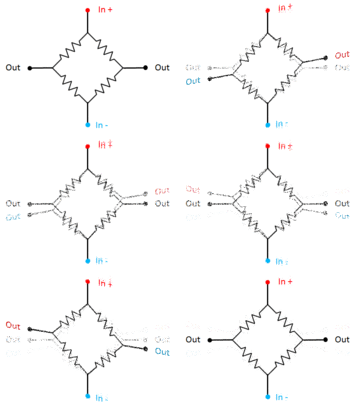
The strain gauges are normally arranged in a Wheatstone bridge circuit as shown in the animation. A voltage is applied to the top and bottom. Because of the symmetry of the circuit, in the rest position the two output terminals will be at exactly the same voltage, and a voltmeter connected between them would register nothing. But when it is stressed, stretching two opposite strain gauges and compressing the other two, it's put out of balance and a voltage appears between the output terminals.
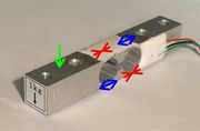
A bar-type load cell is shown in the photo. This has 2 strain gauges on the top and two on the bottom.
At first sight, applying a load to it (the green arrow) would cause the bar to be bent into an arc, causing the top two strain gauges to be stretched and the lower two to be compressed. Furthermore, the lever effect would mean that the amount of stretch or compression would depend on how far from the end of the bar the load was applied.
However, the shaped hole in the middle has two functions: firstly to concentrate the strain into two relatively thin pieces of metal, and secondly to encourage it to bend into an S-shape rather than as arc. As shown by the arrows, S-shape bending will cause two diagonally opposite strain gauges to be stretched and the other two compressed, whereas any tendency to bend into an arc stretches both strain gauges on one side of the Wheatstone bridge and compresses the other two, which doesn't unbalance it.
Digital luggage scales use a load cell following the same principles, but with an S-shaped piece of metal instead of a bar. If you think of the S-shape as two U-shapes joined by one leg, the strain gauges are placed on opposite sides of the bottoms of the two U's.
Half Bridge Load Cells
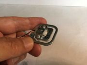
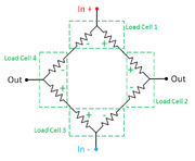
The bar-type load cells contain 4 strain gauges in a "full bridge" configuration and has 4 wires, but bathroom scales commonly use 4 load cells, each with only 3 wires and each containing just 2 strain gauges at either end of a strip of metal. These are known as "half-bridge" load cells.
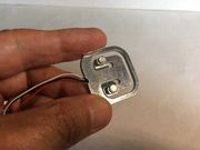
In the photos you can see the strip of metal joining the inner and outer sections and running under a bridging piece which takes the load. The geometry is such that again, the strip is bent into an S-shape.
These are still wired in a Wheatstone bridge, but each of the 4 arms of the bridge contains 2 strain gauges, one from each of 2 adjacent load cells stressed in the same sense, as shown in the diagram. The total imbalance of the Wheatstone bridge is then the sum of the imbalances of the 4 load cells, whether or not the load is evenly distributed amongst them.
Fault-finding and Repair
As stated at the outset, there is little to go wrong apart from physical damage, but as with all battery operated equipment it goes without saying to check the battery is good and the problem isn't battery contacts corroded by leakage from a dead battery.
Check there is nothing obstructing the load cell or cells and their wires aren't broken. The wires are often quite thin. The wires should be routed neatly from the load cell or load cells to the circuit board, ideally, lightly twisted together. If excessively long and loosely routed it is possible that nearby mains wiring could induce currents which could cause inaccurate or inconsistent readings.
Missing rows of pixels on the display can be caused by poor contact between the LCD and the circuit board it's mounted on. Sometimes the connection is made by a strip of conductive rubber which only conducts across its width and not along its length. If you can somehow increase the pressure or clean both the circuit board and the contact area of the LCD you may be able to improve it.
Push buttons can become unreliable with use. Often, the button on the control panel is simply a piece of plastic which actuates a tactile push button switch underneath. These are readily available in a range of fairly standard sizes.
If the readings are consistently inaccurate, make sure you can zero the display (with a Zero or Tare button), otherwise it may need recalibrating. Any scales used commercially must have a means of calibration but on cheap domestic scales such a function may be hidden or non-existent. Look for any hidden buttons, switches or jumpers inside or any menu options labelled Cal or Calibrate. Also, check a manufacturer's website if possible. You will need something of known weight to perform the calibration procedure.
Identifying load cell connections
Should you need to identify the connections to a load cell (for example if 2 or more are broken) you can do so quite easily with a multimeter on a 2kΩ resistance range.
For a half-bridge load cell (3 wires only), this contains just 2 strain gauges. Find one wire that measures the same resistance to either of the other two. This is the centre point of the two strain gauges, and the resistance between those other two should read twice as much. Wiring 4 such load cells into a Wheatstone bridge, the 4 centre points are the + and - inputs, and the two outputs. Th other wires are all connected in pairs of the same colour (see the diagram earlier).
A full bridge load cell has 4 wires and contains 4 strain gauges in a Wheatstone bridge. Measure the resistance from any one wire to each of the other three in turn. One should measure more than the other two, to be precise, two and two thirds as much. This is the opposite corner of the bridge. It doesn't matter which pair of corners you use as + and - inputs and which as outputs, but if the scales give negative weights, just swap the two wires of one pair.

