Connectors (Internal)
There are many different types of connector that you may come across inside a gadget, and in this page we show you how to safely disconnect and reconnect them.
Summary
Nearly all electrical and electronic equipment contains connectors. Some of these are very small or have latches or clamps to keep them connected. You can save frustration and possibly causing damage by being prepared for whatever you might meet.
If you're interested in the plugs and sockets found on the outsides of devices, it's the Connectors (External) page you want.
Safety
- Equipment should be powered off before connectors are disengaged or re-engaged since all the connections in a multi-way connector may not be made or broken at precisely the same time. This could potentially cause damaging voltages or currents in the device.
Introduction
Connectors allow a device or appliance to be built out of various parts, modules or sub-assemblies which can be easily put together on an assembly line, but also allowing them to be taken apart for repair. A connector must provide a good electrical contact rated for the voltages and currents involved, must resist coming undone if subject to vibration or stress, and must fit within the physical size constraints of the device it serves. There are many different types of connectors which meet these demands in different ways.
Full size connectors
The connectors in household and kitchen appliances and power tools rarely cause problems except that they may be very stiff to undo. Occasionally they may have latches, which might not be immediately obvious, to prevent them accidentally coming adrift. (This is very common in vehicle electrics, which is likely to be subject to vibration.)
Screw and spring connectors
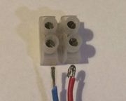
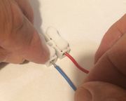
Simple screw terminals are familiar to most people who have ever seen inside a mains plug or switch. Sometimes the wire is wrapped around the screw and clamped by the screw head, preferably under a washer. For a more reliable connection, a fork or ring terminal may be crimped to the end of the wire. More often, as in "choc block" connectors and many types of mains connector, the wire is inserted into a hole in a piece of brass and gripped by a screw.
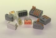
Instead of a screw clamping the wire in the hole, some connectors simply use a piece of springy metal angled so that a wire can be pushed past it but is only gripped more tightly if you try to pull it out. This makes for a very reliable and quickly made connection. Some only work with a solid core wire stiff enough to push past the spring, whereas on others, there is a release mechanism allowing flexible stranded wire to be used.
There are several variations on the basic principal. How to releasse the spring in order to remove the wire isn't always obvious. Sometimes there's a tab you can press to release it, such as the speaker connectors on some music centres, or there may be a clamping lever, such as in some Wago connectors. Slightly more subtle, there may be an inconspicuous button that you can press, or a small hole or slot into which you can push a small screwdriver blade in order to force back the spring. In others (such as push-to-connect Wago connectors) you have to twist the wire back and forth while pulling firmly until it comes out. If you can find no other means of release, the only way is to use a pin or very small screwdriver inserted beside the wire against the spring.
These types of connector have been seen on domestic electrical appliances such as on the main on/off switch, and are common inside flourescent light fittings. Unless you are prepared you can find yourself scratching your head for a while.
Crimp terminals
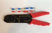
There are several types of crimp terminals which are colour coded according to the diameter of wire they are intended for.
Spade terminals are very commonly found in domestic appliances, and simply consist of a flat piece of metal like a garden spade (though obviously much smaller). It may be attached to or part of a switch, an electric motor, or some other component, and a receptacle slides onto it to make a connection. After a number of years these can become very stiff to remove.
Fork and ring terminals are used for terminating a wire which is to be connected under a screw.
Male and female bullet terminals allow an in-line connection between two wires.
Latched connectors
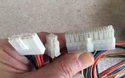
Quite commonly, a connector has a latch of some kind to prevent it shaking or being pulled loose. They are very common in automotive electrics where continual vibration could cause a connector to shake loose, but they are often seen in domestic items as well, particularly for power connectors. The connectors used to connect a standard desktop computer power supply to the motherboard are of this type.
If a connector refuses to disengage, never pull hard on the wires, as they may break or pull out of the connector. Look for some kind of latch or catch. There are various types and you may have to examine it closely in order to determine how to pull, push, squeeze or lever it. Pulling on the connector as you squeeze the latch may prevent the latch from disengaging. Try squeezing then pulling. Sometimes a small flat screwdriver judiciously applied will help.
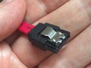
Some SATA disk data cables also have a latch, which you have to squeeze, sometimes quite hard, in order to release.
Miniature connectors
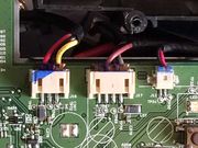
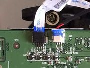
JST and similar connectors are often used to connect multiple wires to a circuit board. They come in different sizes, some of them very tiny. To release them, never just pull on the wires as they may break or come away from the connector. The plug is slightly wider at the top allowing you, instead, to pull on it with your fingernails, or for the smaller ones, tweezers whilst pulling gently on the wires. Pulling alternately on the two ends of the plug often helps.
RF Connectors
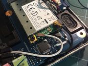
Smartphones, tablets, laptops, WiFi routers and drones often use miniature co-axial plugs and sockets known as U.FL to connect aerial leads to the circuit board. The socket is always surface mounted onto the circuit board and the plugs are not rewireable, only being available factory-connected to a length of miniature high quality co-axial cable. Gently lift off the plug with a fingernail or plastic opening tool. For reconnection, firm finger pressure will cause the plug to mate with a snap you can generally feel. If it doesn't mate it invariably means it's misaligned. Forcing it will only damage the plug and/or the socket.
Ribbon connectors
Flexible ribbons with conducting tracks are extensively used in portable electronic equipment such as cameras, laptops, smartphones and tablets. There are two types.
- FPC (Flexible Printed Circuit) are brown or deep orange and have printed circuit tracks on them and often also have components or connectors mounted directly on them. They are custom made for a particular device.
- FFC (Flexible Flat Cable) have parallel tracks, exposed and tinned or gold plated at each end. These are more of a commodity item, and if needed, you may be able to find a suitable replacement by searching online. They may be advertised as "forward" (the contacts on the same side at both ends of the ribbon) or "reverse" (contacts on opposite sides) and commonly come in pitches or 0.5 or 1mm.
Several types of connector are used to connect these to a circuit board.
Push-fit connectors
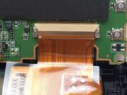
In the simplest type of ribbon connector the end of an FFC ribbon simply pushed into a connector containing contacts which grip it from both sides. The ribbon is reinforced by a slightly stiffer layer bonded to it. These connectors are common in radios and hifi equipment.
Before attempting to disconnect it, first make sure it isn't a zero insertion force connector with a locking mechanism (see below). If not, pull on the reinforcing plastic if you can with tweezers, otherwise pull gently on the ribbon itself.
To reconnect it, simply push the ribbon into the slot in the connector by pushing on the reinforcement if you can. The slot is a millimetre or less off the board and it sometimes takes just a little bit of fiddling to find it. Make sure the ribbon is pushed fully home. There may be a line printed on the ribbon which shows how far the ribbon is meant to go into the connector.
Zero insertion force (ZIF) connectors
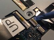
Other types of ribbon connector don't have a plug attached to the ribbon, but instead, the conducting tracks are exposed at the end and often gold plated. The end of the ribbon is inserted into the connector and then clamped in place with a small bar.
Note that if you disconnect and reconnect an FFC ribon more than just a few times the the conductors may delaminate from the plastic backing. As a temporary fix you may be able to stick them back down with superglue, but you will need to take extreme care not to get any on the surface where it mates with the connector.
There are two types. In one, the bar or tab has to be angled up with a fingernail or plastic opening tool to release the ribbon. In the other, the bar has a tab at each end which has to be pulled away from the body of the socket.
In the picture on the left the white bar on the small connector is being lifted. On the larger connector, the black bar has to be lifted.
The picture on the right shows the other type. The grey tabs on either side have to be pushed away from the body of the socket to release the ribbon. Pushing a little on each side alternately often works best.
In all cases the release mechanism is delicate and it's important to establish which sort it is and which parts constitute the clamp. It may be on the ribbon entry side of the connector or on the back. It can normally be opened quite easily once you work out where to lift, pull or push but too much force in the wrong place can cause serious damage. Repair would then involve microsoldering to replace the socket, though there is some chance you could clamp the ribbon by inserting a piece of card or plastic of the right thickness into the connector on the opposite side to the connections.
On reassembly it may take a little fiddling to get the ribbon to go into a narrow slot in the connector. Make sure the release bar is in the fully open position and that the ribbon is fully home before closing the clamping bar.
Snap-on connectors
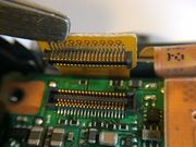
A multi-way plug soldered to the ribbon mates with a socket mounted on the circuit board. To release, lift a corner of the plug with a fingernail or plastic opening tool and it should snap open very easily.
Reseating these can be a little more tricky as the plug and socket need to be correctly aligned, which is often difficult to see as the socket is generally hidden by the ribbon. A little patience may be required to find the correct alignment. Do not try to force it or you may damage it. When correctly aligned, with firm (but not forceful) finger pressure you will be able to feel it snap closed. Press both ends to make sure it's closed along its entire length.
Having closed one of these connectors it can pop open again if the ribbon is strained, for example if it's attached to a sub-assembly which has not yet been screwed back in place.
Battery connectors in smartphones and tablets are often of the snap-on variety, though of larger dimensions. You might think that makes them easier to work with, but this isn't always the case as considerably more force may be required to release them. Applied in the wrong way, this can sometimes cause the socket to detach from the board, which would be hard to repair.
Elastomeric (or ZEBRA) connectors
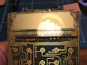
Many devices contain a simple LCD display, usually monochrome, and displaying 7-segment numbers and maybe various status icons, or sometimes a low resolution graphic display. The most familiar examples are DECT and older mobile phones, and pocket calculators.
The LCD is glass and the connections on it are almost invisible conducting tracks deposited on the surface of the glass. An elastometric strip, also known as a ZEBRA connector, is a very simple and common method of making the connections between the display and a printed circuit board. The board has a row of contacts exactly matching those on the LCD and the elastometric strip is sandwiched between them. This consists of alternating conductive and non-conductive segments of silicone rubber along its length, so connecting the tracks on the glass to those on the circuit board beneath. With several such layers per connection, no special alignment is needed.
In the photo, the reflection of the room light shows up the tracks on the glass. If you click on it to expand it you can see the conducting layers in the elastomeric strip at roughly 4 times the density.
The elastometric strip is under pressure between the LCD and the circuit board so as to make good contact, but with age it can loose its springiness, typically resulting in some segments of a 7-segment display no longer working, or one or more rows or columns of pixels in a graphic display failing. If you can arrange to increase the pressure on the strip this may help, or you could try gently squashing it in a direction at right angles to the normal pressure before refitting it. If that doesn't work you could try cleaning the elastomeric strip and the pads on the LCD and the circuit board with isopropyl alcohol.
Heat-seal Connectors
Elastomeric connectors are often used where an LCD is mounted directly over a circuit board as in a calculator, but if this doesn't suit the designer's purpose a conductive ribbon is often used, having parallel graphite conductive tracks. This is heat-sealed to the circuit board at one end and to the LCD at the other.
A common fault is for the adhesive to fail, usually after a number of years. A fix (perhaps only temporary) can sometimes be effected by running a smoothing iron on moderate heat over the ribbon at each end in order to try and press down and reattach the adhesive.
If that doesn't work, if the ribbon is long enough and with a lot of patience and not a little luck it can sometimes be possible to cut off the partially detached section of ribbon and reattach the fresh end, having thoroughly cleaned up the LCD or circuit board. The technique is described in this Instructable. Extreme care is required to align the ribbon correctly onto the board or LCD and then to apply even pressure and heat to reattach it.
Anisotropic (z-axis electrically) conductive tape
A similar attachment method for a ribbon to a circuit board uses anisotropic conductive tape. This is loaded with silver particles sufficiently dispersed so that they give little or no conductivity in the plane of the tape but good conductivity through the tape from one side to the other (the so-called z-access), so making the connections between the ribbon and the board or LCD. This was used in the iPod Touch 2G to connect the WiFi flexible printed circuit (FPC) ribbon to the min board. Potentially it could be used to reattach a heat-seal connector, though we do not have any success to report.
Rolls of tape are extremely expensive but short strips are available quite cheaply on online auction sites under the name 3M 9703.
External links
- iFixit has an excellent guide on Recognizing & Disconnecting Cable Connectors.
- The Electronic Connector Book (website and hard-copy book) contains an exhaustive list of hundreds of types of connector.
