How radios work
A brief introduction to how radios work.
Summary
Often, radios can be fixed simply by looking for the sort of problems common to all electronic gadgets, with very little idea of how they actually work. But when that approach fails, it's necessary to have a basic grounding in the theory of operation in order to go deeper. That is what this Wiki page is intended to provide.
We start by looking at the basic theory of radio transmission, then go on to examine how that theory is put into practice in several different types of radio.
Basic radio theory
In theory, you might be able to connect a microphone, through a powerful amplifier, directly to a transmitting aerial. In practice that wouldn't work because (for reasons we'll come to) you'd need an aerial many miles long, and there'd be no way to transmit more than one programme at a time without them getting mixed up.
An Audio Frequency (AF) signal, such as comes out of a microphone or could be fed into a loudspeaker, consists of frequencies in the range 20Hz - 20kHz (20 - 20,000 vibrations per second). In order to transmit it, that signal has to be impressed in some way upon a much higher Radio Frequency (RF) "carrier". There are several ways of doing that, the process being known as "modulation". A radio receiver essentially has two jobs to do: firstly, selection and amplification of the modulated carrier from that station you want to listen to ("tuning", and "demodulation", or recovering and amplifying the audio signal from it.
We'll look at several methods of modulation, then explain how tuning is achieved.
Amplitude Modulation (AM)
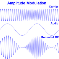
The simplest form of modulation is Amplitude Modulation, or AM. As shown in the diagram, the audio (AF) signal is impressed on the RF carrier as changes in amplitude.
Demodulation is simple. If you were to feed the modulated RF directly into a loudspeaker, you would hear nothing as it's positive just as much as it's negative and the cone would be quite unable to follow the RF oscillations. But if you chop off all the negative bits the net positive that is left will follow the original AF signal, which the speaker will be able to reproduce.
A disadvantage of AM is that it's susceptible to interference from things like a sparking electric motor, a car's ignition system or the fridge turning on and off. These all generate spike of amplitude which the loudspeaker reproduces as clicks.
Frequency Modulation (FM)
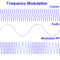
In Frequency modulation or FM, the amplitude of the carrier remains the same but the frequency is varied in sympathy with the audio signal, as shown in the second digram. There are several methods of demodulation and these are generally slightly more complicated than for AM but fortunately we don't need to go into them for the purposes of repair.
An advantage of FM is that any spikes in the signal from interference can simply be chopped off by limiting the amplitude to a maximum value, with the result that they will hardly be heard in the audio output.
Digital Modulation
In digital radio (DAB, or Digital Audio Broadcasting) the audio signal is first converted to digital. The amplitude of the signal (or each channel in the case of stereo) is measured and converted to a binary number many times per second. The absolute minimum rate is twice for every cycle, so for audio containing frequencies up to 20kHz the minimum "sampling rate" as it's called is 40,000 samples per second.
This produces rather a lot of data, but since each sound wave typically only differs slightly from the previous one there is much scope for data compression. This is done by a codec (coder-decoder).
Error correction bits are added to the compressed output of the codec allowing short sequences of corrupted bits to be corrected at the receiving end, and longer sequences to be detected. The resultant data streams from a number of different programmes are then multiplexed together creating an "ensemble" which is used to modulate a carrier.
A digital receiver simply performs all these processes in reverse.
DAB+ is a newer variant which uses a more efficient codec and more powerful error correction, allowing more programmes to be broadcast in a single ensemble. Whilst it allows successful reception of a weaker signal, there is a sharper "cliff edge" where a weak signal degenerates into a burbling noise before being lost.
Types of Radio
Tuned Radio Frequency (TRF)
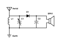
A crystal set is the simplest practical type of radio, and demonstrates some of the basic principles, except that it provides no amplification, relying entirely on the energy delivered by the aerial. The diagram shows a very simple crystal set.
The signal picked up by the aerial is passed to the coil or inductor L1 and the tuning capacitor C1, which form a "tuned circuit". The capacitor stores electrical energy much like a spring stores mechanical energy, and the inductor provides a kind of momentum to a flow of current like the momentum of a heavy object in motion. Just like a weight suspended by a spring, or a pendulum, or a guitar string, the inductor and capacitor have a particular resonant frequency, and tend to reinforce any signal of that frequency coming from the aerial, at the expense of other frequencies. (The arrow through the C1 symbol indicates that it's a variable capacitor, adjustable by a dial on the front panel.)
The diode D1 performs the demodulation, passing current in one direction only. The RF fluctuations are smoothed out by the capacitor C2 leaving us with the original audio signal which is fed to the headphones SPK1.
For a more detailed yet very simple explanation from another age of a crystal set, The Boy's Book of Crystal Sets is well worth looking at.
Apart from poor sensitivity due to the lack of amplification, a crystal set also has poor selectivity, meaning that nearby stations are not well discriminated. This causes a strong station still to be heard while trying to tune in to a nearby weak station and is a result of having only a single tuned circuit.
Amplification can be added either to the AF signal before demodulation, or to the RF signal afterwards, or more usually both. If stages of amplification are added before, then additional tuned circuits can be added before, between and after the stages to improve selectivity. A difficulty arises, though, in that in turning the tuning knob all the tuned circuits must follow one another closely, making it increasingly difficult to design a radio with more than 2 or 3 separate tuned circuits.
Superhet
Digital
External links
- External links (if any) as bullet points.
- If non, delete this section.


