Digital weighing scales
This page covers digital kitchen and bathroom scales. Digital luggage scales follow the same principles of operation.
Summary
There isn't much to go wrong inside digital weighing scales apart from physical problems which should be visible on close inspection. Nevertheless, their principles of operation is interesting, and an understanding will help diagnose any faults which aren't visually obvious.
Principles of operation
Domestic weighing scales use strain gauges to measure the tiny deformations of a piece of metal under load.
A strain gauge is extremely simple. A zigzag resistive track on a foil backing is elongated and becomes thinner as it is stretched (within its elastic limit), which increases its resistance. Conversely, if it is compressed (so long as it doesn't buckle), its resistance is reduced.
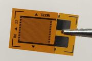
Foil strain gauges like the one shown are normally very securely glued to a piece of aluminium or steel and covered by a protective layer. This causes them to stretch or be compressed with the metal they are mounted on, however, the change in length is only a fraction of a percent at full load. This translates into a change in resistance typically of only twice as much.
A strain gauge will also change its resistance with temperature, and induced currents from nearby mains electric devices may completely swamp the tiny change in resistance. For these reasons, strain gauges in weighing scales are always used in pairs on opposite sides of a piece of metal, causing one to be stretched while the other is compressed. The difference between their resistances is then measured rather than an absolute resistance, allowing other effects to be cancelled out.
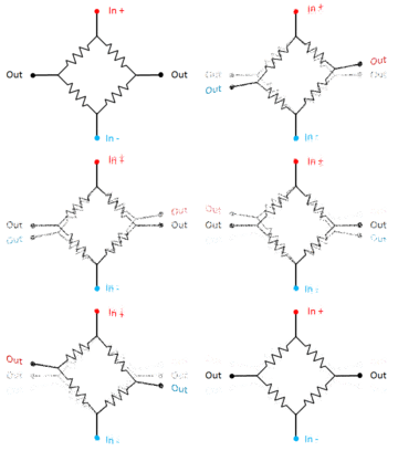
The strain gauges are arranged in a Wheatstone bridge circuit as shown in the animation. A voltage s applied to the top and bottom, and because of the symmetry of the circuit, in the rest position the two output terminals will be at exactly the same voltage, and a voltmeter connected between them would register nothing. But when it is stressed it's put out of balance and a voltage appears between the output terminals.
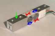
A bar-type load cell is shown in the photo on the right. This has 2 strain gauges on the top and two on the bottom.
At first sight, applying a load to it (the green arrow) would cause the top two strain gauges to be stretched and the lower two to be compressed as the bar is bent into an arc. Furthermore, they would be stretched or compressed more the nearer the end of the bar the load is applied.


