Basic electronic components: Difference between revisions
No edit summary |
|||
| (3 intermediate revisions by the same user not shown) | |||
| Line 115: | Line 115: | ||
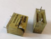
[[File:RIFA_caps.jpeg|200px|thumb|right|A failed and a failing RIFA capacitor.]] | [[File:RIFA_caps.jpeg|200px|thumb|right|A failed and a failing RIFA capacitor.]] | ||
Capacitors connected directly to the mains (generally for interference suppression) require a special safety rating. There are two cases: | Capacitors connected directly to the mains (generally for interference suppression) require a special safety rating. There are two cases: | ||
* Class X are designed to be connected directly between the live and neutral (termed "line to line" or "across the line"). | * Class X are designed to be connected directly between the live and neutral (termed "line to line" or "across the line"). Their design doesn't preclude failure with a short circuit. This could present a fire risk if the circuit isn't adequately protected with a fuse or circuit breaker (not ideal), but there should at least be no electric shock hazard. | ||
* Class Y may be connected between the live and ground (termed "line to ground" or "line bypass"). | * Class Y may be connected between the live and ground (termed "line to ground" or "line bypass"). These are guaranteed not to fail with a short circuit as this would cause the metal frame of the device to become live, creating a lethal shock hazard if there isn't an adequate earth connection. | ||
Such capacitors must always be replaced with ones of the same class. For domestic equipment, sub-class X2 or Y2 are required. You can find out more about Class X and Class Y capacitors in | Such capacitors must always be replaced with ones of the same class. For domestic equipment, sub-class X2 or Y2 are required. You can find out more about Class X and Class Y capacitors in | ||
[https://www.allaboutcircuits.com/technical-articles/safety-capacitor-class-x-and-class-y-capacitors this article]. | [https://www.allaboutcircuits.com/technical-articles/safety-capacitor-class-x-and-class-y-capacitors this article]. | ||
| Line 153: | Line 153: | ||
====Dropper capacitors==== | ====Dropper capacitors==== | ||
Some devices such as kettles, toasters and plug-in time or remote control switches just need a small amount of current at a low voltage to drive electronics or LEDs. A resistor could be used to limit the current but this would generate heat and waste power. | Some devices such as kettles, toasters and plug-in time or remote control switches just need a small amount of current at a low voltage to drive electronics or LEDs. A resistor could be used to limit the current but this would generate heat and waste power. Nevertheless, cheaper vintage valve radios use this approach. All the valve filaments are connected in series, supplied directly from the mains through a resistor capable of dissipating 10 or 20W of power. (Valves intended to be used like this commonly have type numbers starting with P or U.) | ||
A capacitor can do the same job without consuming power; the current is limited to the amount of charge it can hold on each half cycle of the [[Glossary:AC|AC]] mains. But it must be a suitable Class X or Class Y type since it's subject to the full force of the mains supply with whatever voltage spikes and transients come along with it. | |||
The net effect will be that the | Such capacitors are self-healing metalised film types. If a mains surge breaks down the film, the surrounding metalisation instantly burns out, isolating the point of failure. But this means the capacitor may gradually degrade with time. Quite apart from this, the metalisation has been observed to gradually degrade, possibly due to ingress of moisture, likewise causing degradation with time. | ||
The net effect will be that the electronics may no longer work, or work reliably, or maybe the electronics will still work but not enough power will be available to operate a relay or an electromagnet holding the toast down. | |||
As with electrolytic capacitors, they can be very easily tested with an ESR tester. Always replace with a Class X or Y capacitor of the same value. A smaller value may not work and a larger value may stress the electronics. | As with electrolytic capacitors, they can be very easily tested with an ESR tester. Always replace with a Class X or Y capacitor of the same value. A smaller value may not work and a larger value may stress the electronics. | ||
Latest revision as of 17:30, 10 November 2023
This page covers the basic electronic components: resistors, capacitors, inductors, transformers and quartz crystals, how to identify them and understand their common failure modes, and how to test them.
Summary
The most basic electronic circuit elements providing the "furniture" of an electronic circuit are resistors and potentiometers (or variable resistors), capacitors of various sorts, inductors and transformers, and quartz crystals. We describe below how to identify them, what they do, how they sometimes fail and how to test them.
You can read this page on its own if you like, but if you're not already familiar with basic electrical and electronic theory you my find you get more out of it if you first read Electric circuits, volts amps watts and ohms.
Resistors
In many circuits, resistors are the commonest components. They are also generally the cheapest. Their purpose is to resist the flow of electricity, either to limit the current for a given applied voltage (electrical pressure), or to allow a certain voltage (pressure) to build up when a given current flows. Most consist of a thin film of oxide or carbon deposited on a ceramic base. Heat is always generated in a resistor as the current flows, often only a tiny amount but sometimes it can be quite large.
Occasionally you might come across a thermistor, which is a resistor whose resistance decreases markedly with increasing temperature, or a light-dependant resistor (LDR) whose resistance decreases with increasing light levels.
Resistance is measured in Ohms (Ω), kilOhms (kΩ - thousands of Ohms), or megOhms (MΩ - millions of Ohms).
As an interesting aside, whilst resistors may be the commonest and cheapest components in a conventional circuit, they are expensive to fabricate on a silicon chip as they take up a lot of space. Consequently, a chip may contain billions of transistors but few if any resistors at all!
Identification
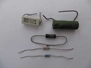
Resistors have 2 leads and very commonly their resistance is denoted by a number of coloured bands (see resistor colour code).
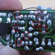
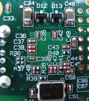
Surface mount resistors are usually black, rectangular, and with a silvery solder pad on each end. They range in size from a few millimetres down to a fraction of a millimetre.
A power resistor is larger than a regular one allowing it to dissipate the required amount of heat. Often, its value will be printed on it instead of being colour coded.
Fault-finding and Repair
Resistors are usually very reliable. When they fail, generally through overheating, it's almost always as a result of some other component failing and causing too much current to flow. In poorly designed equipment having inadequate provision for heat to escape, moderate overheating over a long period of time may cause a failure.
Potentiometers
A potentiometer (or pot, for short) is simply a resistor with a 3rd connection that can be moved to any point along its length, so as to tap off any desired portion of the total resistance.
Identification
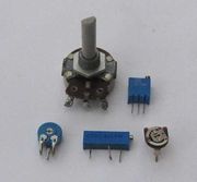
Potentiometers are very commonly used for the volume control in audio equipment (though being superseded by digital controls). These have a spindle with a front panel knob attached, or sometimes a knurled wheel with the edge exposed for adjustment. Twin-gang potentiometers consisting of two mounted on one spindle are often found in stereo equipment for controlling the volume of both stereo channels.
Small potentiometers with a slotted screw head are often found inside equipment for one-time adjustment during manufacture and testing.
Fault-finding and Repair
Potentiometers are much less reliable than fixed resistors. The track can get worn out or crack, or the pressure of the slider on the track can weaken. Sometimes the pressure can be increased by bending the metal slider, though pots are not normally designed to be taken apart and are usually best replaced for a lasting fix.
A quick fix which sometimes works is to squirt switch cleaning fluid into the casing through any gaps or slots you can see, such as beneath the terminals, then repeatedly turn the knob from one end of its travel to the other.
If you find a slotted screw head pot inside a piece of equipment, never adjust it unless you know what it's for and how to find the correct position. Even then, it's worth marking the original position before starting so you can always return to it.
Capacitors
Hopefully you will recall that since like charges repel, electricity hates piling up and as a consequence a circuit must be completed (for example by closing a switch) before a current can flow.
However, electricity will pile up to a limited extent if you apply a voltage (an electrical pressure), but only until the back-pressure equals the voltage you apply.
If there is nowhere much for the electricity to go, that will be very soon, like if you tried to send lots of cars down a short cul-de-sac. But you can make life easier for the electricity if you give it room to spread out, like if there were a large car park at the end of the cul-de-sac. And when you stop pushing the electricity in, it'll all come piling out again as soon as the pressure is released.
A capacitor is a device which allows electricity to pile up by providing space for it to spread out. One of the simplest types just consists of two long strips of aluminium foil separated by a thin insulating strip of plastic, and then rolled up, with a wire connected to each strip. If you connect it to the two terminals of a battery, positive charge will flow out of the positive terminal of the battery and onto one of the strips. Since it's in close proximity to the other strip, it repels an equal amount of positive charge from that strip, which flows back into the negative terminal of the battery. If you disconnect the battery, the electrical charge remains until you connect the two wires together, allowing it to discharge.
A car park has a capacity, but a capacitor has a capacitance. It's measured in Farads (F), or more usually microFarads (μF - millionths of a Farad), nanoFarads (nF - billionths of a Farad), or picoFarads (pF - million-millionths of a Farad).
You can double the capacitance by doubling the surface area that the charge has to spread out in. But you can also do so by halving the thickness of the insulating layer, as this allows the charge on one side to more easily push charge out of the other. But a large enough voltage would destructively break through a very thin insulating layer. A capacitor therefore also has a voltage rating, being the highest voltage that it can safely withstand. This must on no account be exceeded.
Capacitors are used whenever the circuit designer needs to smooth out fluctuations, or when it is required to allow fluctuations (e.g. an audio signal) to flow from one part of a circuit to another whilst blocking any net flow.
Identification
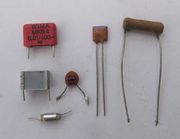
Like resistors, capacitors have just two connections, but they come in a wide range of shapes and sizes. They usually have their capacitance and voltage rating printed on them, and for some types, a maximum temperature.
Low value surface mount capacitors are usually grey or buff in colour, rectangular, and with a silvery solder pad on each end. They are typically a few millimetres in length.
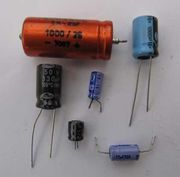
Electrolytic capacitors are very frequently used where a high value of capacitance is required. Much the most common are aluminium types, which can be recognised by the cylindrical aluminium case, usually with a plastic film cover. One lead is marked negative ("-") on the adjacent side or end of the case.
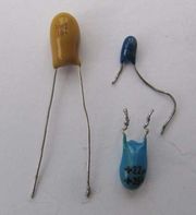
Tantalum capacitors are a higher quality (and more expensive) type of electrolytic capacitor using tantalum instead of aluminium. They come as a resin coated bead. Usually, the positive lead is marked "+".
Capacitors connected directly to the mains (generally for interference suppression) require a special safety rating. There are two cases:
- Class X are designed to be connected directly between the live and neutral (termed "line to line" or "across the line"). Their design doesn't preclude failure with a short circuit. This could present a fire risk if the circuit isn't adequately protected with a fuse or circuit breaker (not ideal), but there should at least be no electric shock hazard.
- Class Y may be connected between the live and ground (termed "line to ground" or "line bypass"). These are guaranteed not to fail with a short circuit as this would cause the metal frame of the device to become live, creating a lethal shock hazard if there isn't an adequate earth connection.
Such capacitors must always be replaced with ones of the same class. For domestic equipment, sub-class X2 or Y2 are required. You can find out more about Class X and Class Y capacitors in this article.
Older equipment predating the X and Y classifications quite often use epoxy-encapsulated RIFA capacitors as illustrated. These will be coming to the end of their lives and should be replaced on sight with modern Class X or Class Y parts.
Fault-finding and Repair
Capacitors are usually very reliable, but there are two exceptions:
- Electrolytic types, which are one of the commonest causes of failure in electronic equipment.
- Dropper capacitors sometimes used to supply a small current at a low voltage for electronic circuits in some appliances.
Electrolytic capacitors
In an electrolytic capacitor, the insulating layer consists of an electrochemically formed film of aluminium oxide with a thickness of only a matter of millionths of a millimetre. This can deteriorate after a long period of disuse (many years) or a shorter period close to or beyond its maximum voltage and/or temperature rating. Also, the liquid used to form the insulating layer can dry out. Poor quality electrolytic capacitors are quite often seen which have failed within their ratings.
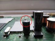
A failing electrolytic capacitor can often be recognised as a build up of internal pressure may cause the top to bulge, or the capacitor no longer to sit flush with the board, or electrolyte to leak from the bottom. At this stage it probably won't be performing well, causing the equipment to malfunction. If not replaced, it may even explode. However the fact that an electrolytic capacitor shows no visible sign of deterioration is by no means a reliable indicator that it's good.
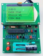
The simplest reliable method of testing an electrolytic capacitor is with an ESR (Equivalent Series Resistance) tester. A basic one with a graphical display but without a case is available very cheaply from Far Eastern sellers. This is an excellent investment as it will also identify and test many other types of component. A good electrolytic capacitor should show an ESR of a fraction of an ohm, and a vloss (another measure given by these testers) of a fraction of a percent.
If an electrolytic capacitor has to be replaced it's very important to fit the replacement the right way round (the "+" or the "-" marking on the same side) as otherwise the electrolytic forming process will be reversed and it will very rapidly fail.
Also, it's always a good idea to replace it with one with a higher voltage and/or temperature rating as the original may have been under-rated. Never ever use a lower rated replacement. If a replacement with the same capacity is not available, a higher value up to twice the original will almost invariably work well, or possibly even better, as there is in any case considerable variation in the capacitance of identically marked electrolytic capacitors.
The site badcaps.net has useful tips on replacing electrolytic capacitors.
Dropper capacitors
Some devices such as kettles, toasters and plug-in time or remote control switches just need a small amount of current at a low voltage to drive electronics or LEDs. A resistor could be used to limit the current but this would generate heat and waste power. Nevertheless, cheaper vintage valve radios use this approach. All the valve filaments are connected in series, supplied directly from the mains through a resistor capable of dissipating 10 or 20W of power. (Valves intended to be used like this commonly have type numbers starting with P or U.)
A capacitor can do the same job without consuming power; the current is limited to the amount of charge it can hold on each half cycle of the AC mains. But it must be a suitable Class X or Class Y type since it's subject to the full force of the mains supply with whatever voltage spikes and transients come along with it.
Such capacitors are self-healing metalised film types. If a mains surge breaks down the film, the surrounding metalisation instantly burns out, isolating the point of failure. But this means the capacitor may gradually degrade with time. Quite apart from this, the metalisation has been observed to gradually degrade, possibly due to ingress of moisture, likewise causing degradation with time.
The net effect will be that the electronics may no longer work, or work reliably, or maybe the electronics will still work but not enough power will be available to operate a relay or an electromagnet holding the toast down.
As with electrolytic capacitors, they can be very easily tested with an ESR tester. Always replace with a Class X or Y capacitor of the same value. A smaller value may not work and a larger value may stress the electronics.
Inductors
An inductor simply consists of a coil of wire. When a current flows it creates a magnetic field, which stores energy. By winding it around a core of magnetic material such as iron or ferrite, this gets magnetised, greatly increasing the amount of energy that is stored.
Whereas a capacitor stores energy in as electrical charge and can be used to smooth out variations in voltage, an inductor stores energy as magnetic flux and tends to smooth out variations in current flow. In such an application it's often called a choke as it chokes variations in the flow.
In fact, there is a beautiful symmetry between the mathematical equations describing capacitors and inductors. If you combine an inductor and a capacitor in a circuit, this symmetry blossoms and something rather special happens. A voltage on the capacitor tries to drive a current through the inductor, but once the current gets going the inductor tries to keep it going, and ends up driving the charge onto the other side of the capacitor. So it flows backwards and forwards at a very regular rate, exactly like a child swinging back and forth on a swing. By using a variable capacitor (or a variable inductor), the rate can be altered. This is how nearly all older AM and FM radios tune in the station you want.
Inductance is measured in Henrys (H), milliHenrys (mH - thousandths of a Henry), or microHenrys (μH - millionths of a Henry).
Identification
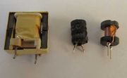
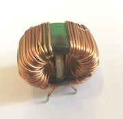
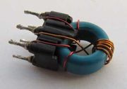
The smallest value inductors consist of no more than a coil of thick wire standing up from the circuit board. Some small inductors consist of a toroid of ferrite with the coil of wire wound around it, and are easily spotted. In others, the coil is wound around a ferrite core shaped like a cotton reel, which may be fitted snugly inside a hollow cylinder of ferrite. A common mode choke has two windings, sometimes used to filter both the live and neutral feeds to a power supply. This then is essentially no different from a transformer.
For large values of inductance a laminated iron core is used. This is rarely seen in reasonably modern equipment, but vintage valve radios often used two large capacitors and an iron-cored inductor to smooth the rectified mains.
An inductor frequently has no markings on it.
Fault-finding and Repair
There is very little to go wrong in an inductor apart from possibly a badly soldered joint. A very heavy current could cause an inductor to overheat or burn out, but probably not before much damage had been done elsewhere in the circuit.
Transformers
A transformer is simply an inductor with two (or more) coils of wire.
An electric current always creates a magnetic field which loops around the current, and a change in the magnetism looping through a circuit generates a voltage in that circuit. So in a transformer, we apply power to one coil of wire, the primary, and the magnetic flux which this creates induces a voltage in the other coil(s), the secondary(s). But it only works while the magnetic field is changing, and so a transformer can only be used for AC, not DC.
Transformers are very useful for two reasons:
- If the secondary coil has more or fewer turns than the primary, the voltage induced in it will be greater or less than that applied to the primary, in proportion.
- Since the only connection between the primary and the secondary is magnetic, they are electrically isolated from each other. This can be useful for safety reasons, or where the circuit designer needs to block a net flow of current from one part to another.
Identification
If you know how to identify an inductor, then a transformer looks exactly the same except that it has at least 3 wires coming out of it, and nearly always 4 or more.
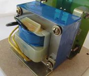
Older mains powered electronic equipment almost always contains an iron cored mains transformer, which is easy to spot. Good quality audio equipment sometimes uses a toroidal mains transformer as this type produces less stray magnetic field and hence less background hum in the audio output. Newer equipment tends to use a much smaller transformer with a ferrite core.
Fault-finding and Repair
Mains transformers may be required to handle a substantial amount of power, and so in fault conditions they can become very hot. If this results in a breakdown of the insulation between two adjacent turns of either the primary or the secondary, these turns will act like a short-circuited secondary and become very hot indeed.
Rewinding a burnt out mains transformer is not difficult, but rarely would be worth the considerable time and patience required.
Crystals and Ceramic Resonators
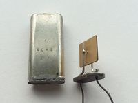
A quartz crystal is commonly used where the designer needs to generate a fixed frequency oscillation. Quartz is a piezoelectric material, which means that a voltage appears across opposite faces if you stress it, and conversely, applying a voltage causes a similar stress. A piece of quartz can be cut and polished so as to resonate (or ring like a bell) at a very precise chosen frequency. Placed in an electronic circuit which amplifies and sustains the resonance, you have a simple and very stable frequency source. The photo shows a crystal that has been removed from its protective can.
Apart from quartz clocks, digital equipment very commonly contains a crystal to provide the oscillation which steps it through its processing steps. In a digitally tuned radio a crystal oscillator generates a reference frequency from which the desired frequency is generated digitally in order to tune the chosen station. Some vintage FM radios contained three crystals in a glass envelope similar to a valve. This allowed three stations to be tuned by selecting one of the three crystals.
Ceramic resonators operate in the same way but are cheaper and less precise in their frequency. These generally use lead zirconium titanate instead of quartz and may be used instead of a crystal in digital equipment where the frequency is not also being used for precise timing. A ceramic resonator may also be used in the IF stages of a radio to select the required frequency. These resonators have 3 leads, one attached to each end of one face of the resonator, and the third attached to the opposite face. The signal is applied to the first and third, causing it to resonate along its whole length. The signal is reproduced between the second and third leads, with any other off-tune frequencies greatly reduced.
Identification
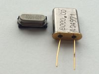
Quartz crystals are usually easy to spot as they come in a silvery metal can. In the case of quartz clocks they are usually cylindrical and quite small. Often, you will see two small capacitors adjacent to a crystal, which are required to allow it to vibrate freely. Occasionally, one of these might be a variable capacitor allowing a fine tuning of its resonant frequency, already accurate to around 10 parts per million.
A ceramic resonator looks very similar to a small capacitor, except that it may have 3 or even 4 leads.
Fault-finding and Repair
Quartz crystals are usually reliable but failures are not unknown. Since the crystal itself is suspended only by its leads to allow it to vibrate freely it can be damaged by shock or vibration, perhaps combined with a weak joint resulting from a manufacturing defect.
There is no simple way of testing a quartz crystal apart from by substitution. A multimeter applied to its leads will show it as an open circuit since quartz is a very good insulator.
And now ...
... you might like to continue by reading about Active components.
