Active components
This page covers active components: diodes and rectifiers, transistors and integrated circuits, how to identify them and understand their common failure modes, and how to test them.
Summary
The "heavy lifters" of electronic components which do the real work are diodes and rectifiers, transistors, and integrated circuits (ICs). We learn how to identify them, what they do, how they sometimes fail and how to test them.
You can read this page on its own if you like, but if you're not already familiar with basic electrical and electronic theory you my find you get more out of it if you first read Electric circuits, volts amps watts and ohms.
Diodes and Rectifiers
Diodes are 2 terminal devices. The commonest types simply allow a current to flow in one direction but not the other. They are very frequently used in power supplies to convert the mains input which is AC (Alternating Current - continually alternating in direction) to DC (Direct Current - which is unidirectional) as required by electronic equipment. In this application they are known as rectifier diodes, and may be called upon to handle a significant amount of power. Schottky diodes are a specialised type used particularly in modern switching mode power supplies which don't use an iron-cored transformer.
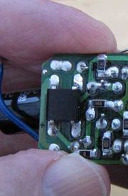
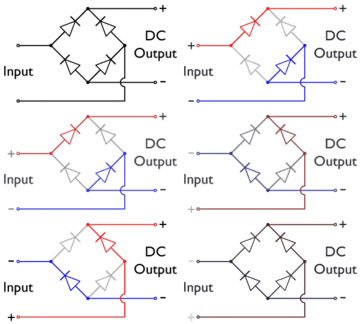
You can convert AC to DC with a single rectifier diode which simply blocks the negative half-cycles, but more often 4 diodes will be used in what is known as a bridge rectifier circuit, which directs both positive and negative half-cycles into the load in the same direction. These 4 diodes may then come in a single package with 4 leads.
Signal diodes are in principle exactly the same, but are used in circuits where the amount of power to be handled is usually very small. They are the key element in a crystal set radio, used to extract the audio from the radio signal, and also find application in logic circuits as well as many other places.
Zener diodes are another specialised type which only block a reverse flow of current up to a well defined voltage. They are used in some power supplies to give a reference voltage against which to set the output voltage.
LEDs (Light Emitting Diodes) are a specialised type in which the energy of electrons passing through them is converted directly into visible or infra-red light.
Identification
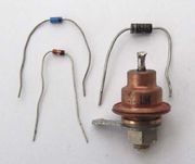
Diodes have 2 leads like resistors, but generally have a painted band around one end. This is the end that positive current flows out of. A very common type of rectifier diode has designation 1N400n, or a higher power version, 1N540n, where "n" is a digit indicating the maximum voltage it can be used for. A clutch of 4 of them or a bridge rectifier in a single 4-legged package will often be seen close to an iron-cored mains transformer, or close to the mains input.
Signal diodes and zener diodes often come in a very small glass package.
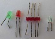
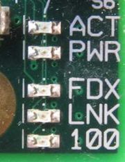
LEDs are easily recognised by their clear or coloured transparent package. Sometimes (for example in toys) a LED will have a silicon chip incorporated in the package to make it flash or flicker, or to eliminate the need for an external resistor. Two or more LEDs are sometimes incorporated in a single package to give multiple colours.
Fault-finding and Repair
Very many digital test meters, even the cheapest, will have a diode test function. Connect the red test lead to the end of the diode with the painted band and the black lead to the other end. Most diodes should give a reading of around 0.7V, except for Shottky diodes for which it will be more like 0.4V. Anything much closer to zero or a low reading with the leads reversed indicates that the diode has failed. A LED on the other hand would give a much higher reading of between 1.8V and 4V, in many cases off the range of a test meter.
LEDs rarely fail unless seriously abused. They can be tested by connecting them across a battery of between 3V and 9V in series with a resistor between 330Ω an 1kΩ. The negative lead is often designated by a flat on the side of the package.
Transistors
Transistors have 3 connections. They are used for amplifying a weak signal, or for switching current on and off. In this section we will also cover thyristors and triacs, which are related.
There are 2 types of transistor:
- Bipolar or Junction transistors. The 3 terminals are known as emitter, base and collector. Current flows from the emitter to the collector, but is only able to in proportion to a much smaller current that you feed into the base.
- Field effect transistors (FETs). In these, the 3 terminals are known as source, gate and drain. Current flows from the source to the drain, but is controlled by the voltage you apply to the gate.
Each type comes in two complementary varieties or polarities: bipolar transistors are either NPN or PNP, and FETs are either N-channel or P-channel. The direction of current flow and the voltages are reversed between the two varieties.
Additionally, FETs come in several types, such as enhancement versus depletion mode, and junction (jFET) versus insulated gate FET.
A thyristor is essentially a PNP and NPN transistor merged into one, and acts like a switch that latches on. A triac does the same job but is designed to work on AC. Dimmer switches contain a triac.
Identification
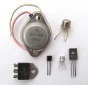
Transistors and their cousins are quite easily recognisable as almost the only components having just 3 legs.
Practically all are marked with their type code, not to be confused with a manufacturing date code or other markings. Looking up the type code with a web search engine and consulting the datasheet is the only visual means of distinguishing bipolar and field effect transistors and determining their polarity, or identifying a thyristor or a triac, and identifying the 3 leads.
A very common family of voltage regulator is only visually distinguishable from a transistor by its type number. This is usually 78 or 79, optionally a letter, and followed by 2 digits, e.g 78L05. These are integrated circuits, discussed later.
Fault-finding and Repair
Many digital test meters, even some of the cheapest, have a transistor test function for bipolar transistors, often marked hFE, and with separate sockets or switch positions for PNP and NPN. Identify the emitter, base and collector, and push them into the appropriate holes in the test socket. A reading can be expected of anything between around 20 and 500.
Alternatively, if your test meter only has a diode test facility, a bipolar transistor can be tested as two diodes. Connect the positive test lead to the base and the negative to the emitter and collector in turn. Both should give a reading of around 0.7V for an NPN transistor or an out of range indication for a PNP. Now connect the negative test lead to the base. This time you should get 0.7V for a PNP or out of range for an NPN. In the case of older germanium transistors from a vintage radio, expect a reading of around 0.3V instead of 0.7V. If any of the readings is much lower than expected, or you get anything but out of range with the test leads between the emitter and collector (whilst not touching the base) then the transistor is dead.
When replacing a transistor it's very important to install the replacement exactly like the original.
An audio amplifier often uses a complementary pair of PNP and NPN transistors in the output stage. These sometimes develop a short circuit between the emitter and collector resulting in a blown fuse. In replacing the transistors, make sure you clean the heat sink and replace any heat conductive paste or insulating washer. If replacing a complementary pair, take great care not to get them muddled up.
Field effect transistors tend to be more robust, but a simple test is to connect a test meter between the gate and the source and drain in turn. An infinite resistance should be indicated, except for a jFET where it will behave like a diode.
Integrated Circuits
The techniques for fabricating multiple electronic components and their interconnections on a silicon chip to form a "integrated circuit" or IC were first developed in the 1960s. They underpin the whole of the modern electronics and information technology revolution and earned the key players a Nobel prize for physics in the year 2000.
There are many thousands of different types of integrated circuits (or ICs) ranging from the simplest types, a few of which have been available for up to 30 - 40 years, up to the latest and most complex, containing billions of circuit elements.
Identification
A few ICs have just 2 or 3 connections. The commonest in this class are voltage regulators, visually very similar to power transistors. They generally have a type designation printed on them consisting of 2 digits "78" or "79", optionally a letter, then 2 more digits indicating the voltage, e.g. 78M05. The 78 types produce a positive regulated voltage, and the 79 types a negative.
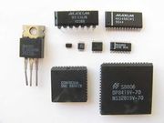
Most ICs have anything from 8 to many hundreds of connections (generally known as pins), usually in a black plastic case. A notch at one end of the case or a dot in the corner indicates which is Pin 1 (other pins are numbered in sequence). All ICs have a type designation printed on the top.
Simpler and commoner ICs come in a "dual in-line" (DIL) package, with a row of pins down each side at 0.1" spacing. In modern equipment, very fine pin spacing is used in surface mounted packages for all the more complex ICs and even many of the simpler ones.
Fault-finding and Repair
ICs can be permanently damaged by static electricity. Whilst they normally contain protection against static up to a certain level, static precautions should be taken for the more expensive and complicated types such as those used in computers, particularly in conditions of low humidity or if nylon carpets or clothing may produce static. These precautions consist of frequently earthing oneself by touching a radiator or an appliance with an earthed metal case, and use of an antistatic wrist strap and mat.
Most ICs are reliable, but failures can result from a fault elsewhere in the circuit, a battery or power supply connected the wrong way around, static, a nearby lightning strike, or a nuclear explosion (but in the latter case you will have other things to worry about). An audio power amplifier IC might fail due to overload or a shorted output.
Voltage regulators and other low pin count devices are easily replaced by another of the same type.
DIL ICs can be removed and replaced with a little care and patience, using a solder sucker and/or solder wick to unsolder the pins. Watch out for any sign of the copper printed circuit tracks lifting from the board and then cracking due to too much heat being applied. This can significantly complicate the repair.
Replacing surface mount ICs is very much more challenging and generally requires professional equipment and considerable skill, though it may be possible in some cases where the pin density isn't too high.
And now ...
... you might like to continue by reading about Optoelectronic components.
