How to use a multimeter: Difference between revisions
| Line 73: | Line 73: | ||
You can also use the diode test function to test a junction [[Active_components#Transistors |transistor]] (though not a field-effect transistor). These have 3 leads, the emitter, base and collector. A good transistor will test as a diode between the base and either of the other two leads. You can determine which lead is which quite easily by trial and error. You should get a reading of around 0.7V between the base and collector and slightly less between the base and emitter. This will be with the red lead on the base for NPN types, and the black lead for PNP. You should get an out of range reading between the emitter and collector, provided the base is not touching anything. A zero reading indicates that the transistor is definitely dead. | You can also use the diode test function to test a junction [[Active_components#Transistors |transistor]] (though not a field-effect transistor). These have 3 leads, the emitter, base and collector. A good transistor will test as a diode between the base and either of the other two leads. You can determine which lead is which quite easily by trial and error. You should get a reading of around 0.7V between the base and collector and slightly less between the base and emitter. This will be with the red lead on the base for NPN types, and the black lead for PNP. You should get an out of range reading between the emitter and collector, provided the base is not touching anything. A zero reading indicates that the transistor is definitely dead. | ||
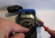
[[File:Img_2175a.jpg|180px|thumb|right|Testing a trnsistor with the | [[File:Img_2175a.jpg|180px|thumb|right|Testing a trnsistor with the h<sub>FE</sub> function.]] | ||
Many multimeters also have a transistor test function (for junction transistors only), labelled Hfe. Hfe is one of the ways of defining the amplification factor the transistor is capable of, but since it can be anything between 20 or less and 500 or more, it's not in itself a measure of the health of a transistor. If it reads zero or out of range, it may well be that you've connected the transistor incorrectly or the leads are failing to make proper contact. | Many multimeters also have a transistor test function (for junction transistors only), labelled Hfe. Hfe is one of the ways of defining the amplification factor the transistor is capable of, but since it can be anything between 20 or less and 500 or more, it's not in itself a measure of the health of a transistor. If it reads zero or out of range, it may well be that you've connected the transistor incorrectly or the leads are failing to make proper contact. | ||
Revision as of 09:05, 6 April 2015
How to use a multimeter. Work in progress - pics/diagrams to be added.
Summary
After a good set of screwdrivers, a multimeter is one of the most useful things you can add to your tool kit. This page describes how to use it for a range of basic tests.
Choosing a multimeter
Multimeters come in two sorts: analogue (with a dial), and much more commonly, digital. There are very few occasions when an analogue multimeter would be better, and the digital variety is in any case much more robust.
Apart from a multimeter designed mainly for auto-electrics, even the cheapest (under £5 on eBay) will have most if not all the functions you will need commonly.
The minimum functions you should look for are DC Volts (2V up to 200V), AC Volts (500V) and resistance (200Ω up to 2000kΩ).
Less useful but very common are DC current ranges (2mA up to 200mA).
Some multimeters are auto-ranging, which means they have only one DC Volts range and automatically adjust according to the voltage applied, and similarly for current and resistance.
A continuity function is very useful. This makes a beeping sound when the probes find a low resistance path between them.
A diode test function is also very useful. A transistor test function is common (indicated by hFE) but less useful in practice.
Most multimeters come with a pair of test leads with pointy ends. These are good, for example, for touching on two points on a circuit board or a piece of equipment, but an additional pair with crocodile clips are also very useful. You can use these to clip onto the leads of a component or any other exposed wires or connectors, leaving your hands free.
Before you start
Many multimeters have an "Off" position on the range switch, but others have a separate on/off switch. Be sure to switch it off after use - if you leave it switched on in your tool box you may well find the battery is dead the next time you need it.
Often, the range switch has separate settings for AC and DC ranges, but if there is a separate AC/DC switch, make sure it's always in the DC position except when you're measuring AC, or you will get misleading readings.
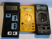
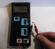
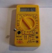
Check how your multimeter displays an out of range condition. This is when the value to be measured is too great for the number of digits to the left of the decimal point on the display. Put it on any of the resistance (Ω, or Ohms) ranges don't touch the test probes on anything. It may display "OL" (Overload), or "1 ." (see the photo above), or something else other than a proper number.
On DC voltage and current ranges, you should apply the red test probe to the positive and the black to the negative. But if you connect them the other way round you'll simply get a negative reading.
Measuring Voltage
Testing a battery
For a C, AA or AAA battery or a button cell (but not a lithium one), set the range switch to 2V, or for a lithium or PP3 battery or if you're not sure, set it to 20V. Apply the test probes, the red to the positive terminal.
A rechargeable battery should read around 1.2V, or a little above when freshly charged, and dropping to 1V when needing to be recharged. Others (including most button cells) will read around 1.5V or a little above when new, dropping steadily with use. Depending on the demands of the application they may be serviceable down to 1.2 or 1.0V.
For other batteries such as all lithium types and 9V PP3 batteries you will need the 20V range. Apply the test probes in the same way. Lithium batteries should read between 3 and 3.7V depending on the type, except for laptop and power tool batteries which contain a number of cells in series and should read about 3.6V times the number of cells. A 9V PP3 battery will drop to 6 or 7V at the end of its life.
Testing equipment
For a mains adapter or charger, check the label on the device to see what its output is supposed to be and whether the output is AC or DC. Select the next range (AC or DC) which is higher than the rated output. Cheap unregulated adapters may register considerably more than their rated output with no load.
You can check the voltages inside a piece of equipment to see whether power is getting through. You should never operate mains powered equipment with the covers off unless you fully understand the dangers and can do so without risk to yourself or any bystanders.
For equipment containing an iron mains transformer, if you can do so safely you should be able to measure (with care!) the mains coming in to the primary of the transformer at 240V AC and reduced to a much lower voltage AC on the secondary, then rectified and smoothed to a similar DC voltage, and finally, perhaps, regulated to a stable voltage such as 12V or 5V. See the page on Power Supplies for more details.
Switch mode power supplies (containing a small ferrite transformer) are more complicated to test.
Measuring Continuity and Resistance
The resistance (Ω or Ohms) ranges measure resistance. This is a measure of how easily an electric current can pass. With the probes not touching anything you should bet an out of range condition.
As an experiment, put the multimeter on the highest Ω range and hold the two probe tips in the fingers of each hand. If you don't get a reading, hold the probe tips more tightly or moisten your fingers. You will find the reading decreases as you grip the probes more tightly and the resistance through your body is reduced. (Yes, electricity is passing through your body, but this is no more dangerous than handling an AA battery.)
Touch the probe tips together. You should get a zero reading on any of the resistance ranges as there is now virtually no resistance to the current flow between the probes.
The lowest resistance range may also be a continuity tester, producing a beep when you touch the probes together. In fact, continuity testing is probably the most useful function of the resistance ranges allowing you to test whether a current can flow easily between two points A and B, such as the two ends of a lead.
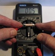
You can use the continuity test function or the lowest resistance range to test a fuse. Touch the probes on the two ends and see if you get a beep or a zero (or very low) reading, indicating that it is good. A blown fuse will give an out of range reading.
You can test a filament light bulb (a halogen bulb or a replaceable Christmas tree light bulb, but not a low energy bulb) with the lowest or next to lowest resistance range. You should get a reading of tens or hundreds of ohms only. (This is the resistance of the filament when cold. At working temperature, the resistance may increase ten-fold or more.)
You can test resistors with the resistance ranges, but soldered onto a circuit board, the path through the resistor itself may not be the only electrical path between its ends, resulting in misleading results. Furthermore, there is some chance that the voltage applied by the multimeter in order to measure a resistance could damage sensitive electronic components. If you can borrow another multimeter, connect the probes of yours, set to a resistance range, to the probes of the other, set to a low Volts range. If the reading on the second multimeter is no more than 0.5V with the first on any of the resistance ranges then it cannot do any damage.
Diode and Transistor testing
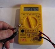
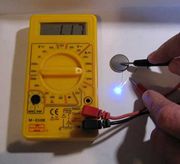
Power supplies normally contain diodes, often in a group of 4. You can test these with your multimeter on the diode test range. With the probes connected to the ends of the diode one way round you should get an out of range reading, and the other way a reading of around 0.7V, or for some types, as low as 0.3V. A zero reading either way round or an out of range reading in both directions indicates a faulty diode.
You can also use the diode test function to test a junction transistor (though not a field-effect transistor). These have 3 leads, the emitter, base and collector. A good transistor will test as a diode between the base and either of the other two leads. You can determine which lead is which quite easily by trial and error. You should get a reading of around 0.7V between the base and collector and slightly less between the base and emitter. This will be with the red lead on the base for NPN types, and the black lead for PNP. You should get an out of range reading between the emitter and collector, provided the base is not touching anything. A zero reading indicates that the transistor is definitely dead.
Many multimeters also have a transistor test function (for junction transistors only), labelled Hfe. Hfe is one of the ways of defining the amplification factor the transistor is capable of, but since it can be anything between 20 or less and 500 or more, it's not in itself a measure of the health of a transistor. If it reads zero or out of range, it may well be that you've connected the transistor incorrectly or the leads are failing to make proper contact.
Multimeters generally have 4 contacts for the emitter, base and collector (marked E, B, C) with one duplicated, simply for convenience since some transistors have the leads in the order E, B, C and others E, C, B. There will either be separate ranges for NPN and PNP, or two sets of 4 contacts. On account of the variability of lead thicknesses and the lack of flexibility of short leads on a transistor unsoldered from a circuit board, it isn't always easy to make good contact with all three leads.
Measuring Current
You will not often need to measure current (the Amps ranges), but when you do, it's very important to understand that you must break the circuit and place the test probes across the break, so that the current has to pass through the multimeter. If you connect it directly across a supply such as the terminals of a battery, it will offer very little resistance and an excessive current will flow, with the possibility of damaging the multimeter or the equipment under test.
You can, for example, test how much current a battery powered radio is taking and so determine how long you can expect the batteries to last. Breaking the circuit can be a little tricky but one way to do it is to glue a strip of aluminium foil to each side of a piece of paper, making sure there is no contact between the two pieces of foil, then inserting it between two of the batteries, or one of them and the battery compartment contact. You can now touch the multimeter probes onto the two pieces of foil in order to complete the circuit and allow you to switch the radio on. If, for example, the radio takes 200mA and the batteries are rated as 2000mAh (milliamp-hours) they should last about 10 hours.
Safety
Consider whether your page should include a specific section on safety, if for example it deals with mains-powered equipment or high voltages, or if special care is required in handling hot or sharp tools, or hazardous substances.
References
External links
- External links as bullet points
