Basic electronic components/nl: Difference between revisions
(Created page with "Af en toe kunt u een weerstand met een negatieve temperatuurcoëfficiënt (NTC) tegenkomen. Dat is een weerstand waarvan de weerstand duidelijk afneemt bij toenemende temperatuur, of een lichtafhankelijke weerstand (LDR) waarvan de weerstand afneemt bij toenemend licht.") |
(Created page with "180px|thumb|right|Potentiometers. Een potentiometer (of kortweg pot) is een weerstand met een derde aansluiting die naar elk punt van zijn lengte kan worden bewogen, zodat elk gewenst deel van de totale weerstand kan worden afgetapt.") |
||
| Line 64: | Line 64: | ||
[[File:Img_1906a.jpg|180px|thumb|left|Elektrolytische condensatoren.]]Als er geen weerstand is in de stroomkring, zal de spanning over de condensator heel snel de maximumwaarde bereiken. Hoe groter de condensator (maw hoe groter de capaciteit) hoe langer dit duurt. | [[File:Img_1906a.jpg|180px|thumb|left|Elektrolytische condensatoren.]]Als er geen weerstand is in de stroomkring, zal de spanning over de condensator heel snel de maximumwaarde bereiken. Hoe groter de condensator (maw hoe groter de capaciteit) hoe langer dit duurt. | ||
[[File:Img_1907a.jpg|180px|thumb|right|Tantaal condensatoren.]] | |||
[[File:Img_1907a.jpg|180px|thumb|right| | Een condensator is een apparaat dat elektriciteit laat opstapelen door het ruimte te geven. Een van de eenvoudigste types bestaat gewoon uit twee lange stroken aluminiumfolie, gescheiden door een dunne isolerende strook plastic, en dan opgerold, met een draad verbonden met elke strook. Als je die aansluit op de twee polen van een batterij, stroomt er positieve lading uit de positieve pool van de batterij naar een van de stroken. Omdat hij dicht bij de andere strook ligt, stoot hij evenveel positieve lading van die strook af, die terugvloeit naar de negatieve pool van de batterij. Als u de accu loskoppelt, blijft de elektrische lading bestaan totdat u de twee draden met elkaar verbindt, zodat deze zich kan ontladen. | ||
De grootte van een condensator wordt aangeduid als de capaciteit. Die wordt uitgedrukt in Farads (F), of meestal in microFarads (μF - miljoenste van een Farad), nanoFarads (nF - miljardste van een Farad), of picoFarads (pF - miljoenste van een Farad). | |||
U kunt de capaciteit verdubbelen door het oppervlak waarover de lading zich moet verspreiden te verdubbelen. Maar dat kan ook door de dikte van de isolerende laag te halveren, want daardoor kan de lading aan de ene kant gemakkelijker lading uit de andere kant duwen. Maar een voldoende grote spanning zou een zeer dunne isolatielaag destructief doorbreken. Een condensator heeft daarom ook een doorslagspanningswaarde, namelijk de hoogste spanning die hij veilig kan verdragen. Deze mag in geen geval worden overschreden. | |||
Condensatoren worden gebruikt wanneer de circuitontwerper fluctuaties moet afvlakken, of wanneer het nodig is fluctuaties (b.v. een audiosignaal) van het ene deel van een circuit naar het andere te laten stromen, terwijl elke gelijkstroom wordt geblokkeerd. | |||
===Identificatie=== | |||
=== | |||
Net als weerstanden hebben condensatoren slechts twee aansluitingen, maar ze zijn er in allerlei vormen en maten. Op de condensator staat meestal de capaciteit en de doorslagspanning vermeld en voor sommige types ook de maximum temperatuur. | |||
Opbouwcondensatoren (SMD) met een lage waarde zijn meestal grijs of geelbruin van kleur, rechthoekig en met een zilverkleurig soldeerpad aan elk uiteinde. Ze zijn meestal een paar millimeter lang. | |||
<div lang="en" dir="ltr" class="mw-content-ltr"> | <div lang="en" dir="ltr" class="mw-content-ltr"> | ||
Revision as of 09:06, 3 February 2023
Deze pagina behandelt de elektronische basiscomponenten: weerstanden, condensatoren, spoelen, transformatoren en kwartskristallen, hoe ze te identificeren en hun algemene storingen te begrijpen, en hoe ze te testen.
Samenvatting
De meest elementaire elementen die de basis van een elektronische schakeling vormen zijn weerstanden en potentiometers (of regelbare weerstanden), verschillende soorten condensatoren, spoelen en transformatoren, en kwartskristallen. We beschrijven hieronder hoe u ze kunt identificeren, wat ze doen, hoe ze soms falen en hoe u ze kunt testen.
U kunt deze pagina op zichzelf lezen, maar als u nog niet vertrouwd bent met elektrische en elektronische basistheorie zult u merken dat u er meer aan hebt als u eerst Elektrische schakelingen, Volt, Ampère, Watt en Ohm leest.
Weerstanden
In veel schakelingen zijn weerstanden de meest voorkomende componenten. Ze zijn over het algemeen ook het goedkoopst. Hun doel is om de stroom bij een bepaalde spanning te beperken of om een bepaalde spanning te laten ontstaan bij een bepaalde stroom. De meeste bestaan uit een dunne laag oxide of koolstof, afgezet op een keramische basis. In een weerstand ontstaat altijd warmte als de stroom vloeit, vaak slechts een kleine hoeveelheid, maar soms kan de warmte vrij groot zijn.
Af en toe kunt u een weerstand met een negatieve temperatuurcoëfficiënt (NTC) tegenkomen. Dat is een weerstand waarvan de weerstand duidelijk afneemt bij toenemende temperatuur, of een lichtafhankelijke weerstand (LDR) waarvan de weerstand afneemt bij toenemend licht.
De weerstand wordt gemeten in Ohm (Ω), kiloOhm (kΩ - duizend Ohm) of MegaOhm (MΩ - miljoen Ohm).
Terzijde: weerstanden zijn weliswaar de meest voorkomende en goedkoopste componenten in een conventioneel circuit, maar ze zijn duur om op een siliciumchip te fabriceren omdat ze veel ruimte innemen. Bijgevolg kan een chip miljarden transistors bevatten maar weinig of geen weerstanden!
Identificatie
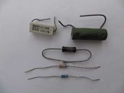
Weerstanden hebben 2 draden en hun weerstand wordt meestal aangegeven door een aantal gekleurde banden (zie kleurcode van de weerstand).
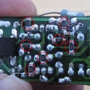
Opbouwweerstanden (SMD) zijn meestal zwart, rechthoekig en met een zilverkleurig soldeerplaatje aan elk uiteinde. Zej variëren in grootte van enkele millimeters tot een fractie van een millimeter.
Een vermogensweerstand is groter dan een gewone, zodat hij de vereiste hoeveelheid warmte kan afvoeren. Vaak staat de waarde erop gedrukt in plaats van met een kleurcode aangegeven.
Foutopsporing en reparatie
Weerstanden zijn meestal zeer betrouwbaar. Als ze uitvallen, meestal door oververhitting, is dat bijna altijd het gevolg van een ander defect onderdeel waardoor er te veel stroom gaat lopen. In slecht ontworpen apparatuur met onvoldoende voorzieningen voor warmteafvoer kan matige oververhitting over een lange periode een storing veroorzaken.
Potentiometers
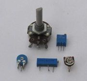
Een potentiometer (of kortweg pot) is een weerstand met een derde aansluiting die naar elk punt van zijn lengte kan worden bewogen, zodat elk gewenst deel van de totale weerstand kan worden afgetapt.
Identificatie
Potentiometers worden zeer vaak gebruikt voor de volumeregeling in audioapparatuur (hoewel tegenwoordige digitale regelaars worden gebruikt). Deze hebben een spindel met een knop aan de voorzijde, of soms een gekarteld wieltje waarvan de rand blootligt om te worden ingesteld. Dubbele potentiometers bestaan uit twee op één spindel gemonteerde potentiometers. Ze worden vaak aangetroffen in stereoapparatuur voor het regelen van het volume van beide stereokanalen.
Kleine potentiometers met een gegroefde schroefkop worden vaak aangetroffen in apparatuur voor eenmalige afstelling tijdens fabricage en testen.
Foutopsporing en reparatie
Potentiometers zijn veel minder betrouwbaar dan vaste weerstanden. De baan kan versleten raken of barsten, of de druk van de schuifknop op de baan kan verzwakken. Soms kan de druk worden verhoogd door het metalen schuifje te buigen, maar potmeters zijn normaal gesproken niet ontworpen om uit elkaar te worden gehaald en kunnen het best worden vervangen voor een duurzame oplossing.
Een snelle oplossing die soms werkt is om reinigingsvloeistof voor de schakelaar in de behuizing te spuiten via eventuele openingen of gleuven die u kunt zien, zoals onder de terminals, en dan de knop herhaaldelijk van de ene naar de andere kant te draaien.
Als u in een apparaat een schroefkop met gleuf vindt, stel deze dan nooit bij, tenzij u weet waarvoor hij dient en hoe u de juiste positie kunt vinden. Zelfs dan kunt u best de oorspronkelijke positie markeren voordat u begint, zodat u er altijd naar terug kunt keren.
Condensatoren
Als er een spanning over een condensator staat, bevat de ene plaat vooral negatieve ladingen en de andere vooral positieve. Omdat gelijkvormige ladingen elkaar afstoten, loopt er stroom bij het sluiten van het circuit (bv door een schakelaar te sluiten).
Elektriciteit stapelt zich in beperkte mate op over de condensator als je een spanning uitoefent. Dit is het opladen van de condensator.
Als er geen weerstand is in de stroomkring, zal de spanning over de condensator heel snel de maximumwaarde bereiken. Hoe groter de condensator (maw hoe groter de capaciteit) hoe langer dit duurt.
Een condensator is een apparaat dat elektriciteit laat opstapelen door het ruimte te geven. Een van de eenvoudigste types bestaat gewoon uit twee lange stroken aluminiumfolie, gescheiden door een dunne isolerende strook plastic, en dan opgerold, met een draad verbonden met elke strook. Als je die aansluit op de twee polen van een batterij, stroomt er positieve lading uit de positieve pool van de batterij naar een van de stroken. Omdat hij dicht bij de andere strook ligt, stoot hij evenveel positieve lading van die strook af, die terugvloeit naar de negatieve pool van de batterij. Als u de accu loskoppelt, blijft de elektrische lading bestaan totdat u de twee draden met elkaar verbindt, zodat deze zich kan ontladen.
De grootte van een condensator wordt aangeduid als de capaciteit. Die wordt uitgedrukt in Farads (F), of meestal in microFarads (μF - miljoenste van een Farad), nanoFarads (nF - miljardste van een Farad), of picoFarads (pF - miljoenste van een Farad).
U kunt de capaciteit verdubbelen door het oppervlak waarover de lading zich moet verspreiden te verdubbelen. Maar dat kan ook door de dikte van de isolerende laag te halveren, want daardoor kan de lading aan de ene kant gemakkelijker lading uit de andere kant duwen. Maar een voldoende grote spanning zou een zeer dunne isolatielaag destructief doorbreken. Een condensator heeft daarom ook een doorslagspanningswaarde, namelijk de hoogste spanning die hij veilig kan verdragen. Deze mag in geen geval worden overschreden.
Condensatoren worden gebruikt wanneer de circuitontwerper fluctuaties moet afvlakken, of wanneer het nodig is fluctuaties (b.v. een audiosignaal) van het ene deel van een circuit naar het andere te laten stromen, terwijl elke gelijkstroom wordt geblokkeerd.
Identificatie
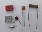
Net als weerstanden hebben condensatoren slechts twee aansluitingen, maar ze zijn er in allerlei vormen en maten. Op de condensator staat meestal de capaciteit en de doorslagspanning vermeld en voor sommige types ook de maximum temperatuur.
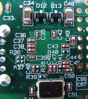
Opbouwcondensatoren (SMD) met een lage waarde zijn meestal grijs of geelbruin van kleur, rechthoekig en met een zilverkleurig soldeerpad aan elk uiteinde. Ze zijn meestal een paar millimeter lang.
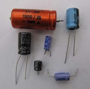
Electrolytic capacitors are very frequently used where a high value of capacitance is required. Much the most common are aluminium types, which can be recognised by the cylindrical aluminium case, usually with a plastic film cover. One lead is marked negative ("-") on the adjacent side or end of the case.
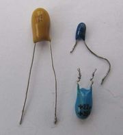
Tantalum capacitors are a higher quality (and more expensive) type of electrolytic capacitor using tantalum instead of aluminium. They come as a resin coated bead. Usually, the positive lead is marked "+".
Capacitors connected directly to the mains require a special safety rating. This is Class X for those connected across the mains supply, where a failure could present a fire hazard, and Class Y for those connected between the mains and ground, where the failure could result in an electric shock hazard. Such capacitors must always be replaced with ones of the same class. For domestic equipment, sub-class X2 or Y2 are required. You can find out more about Class X and Class Y capacitors in this article.
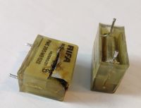
Older equipment predating the X and Y classifications quite often use epoxy-encapsulated RIFA capacitors as illustrated. These will be coming to the end of their lives and should be replaced on sight with modern Class X or Class Y parts.
Fault-finding and Repair
Capacitors are usually very reliable except for electrolytic types, which are one of the commonest causes of failure in electronic equipment.
In an electrolytic capacitor, the insulating layer consists of an electrochemically formed film of aluminium oxide with a thickness of only a matter of millionths of a millimetre. This can deteriorate after a long period of disuse (many years) or a shorter period close to or beyond its maximum voltage and/or temperature rating. Also, the liquid used to form the insulating layer can dry out. Poor quality electrolytic capacitors are quite often seen which have failed within their ratings.
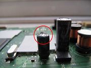
A failing electrolytic capacitor can often be recognised as a build up of internal pressure may cause the top to bulge, or the capacitor no longer to sit flush with the board, or electrolyte to leak from the bottom. At this stage it probably won't be performing well, causing the equipment to malfunction. If not replaced, it may even explode. However the fact that an electrolytic capacitor shows no visible sign of deterioration is by no means a reliable indicator that it's good.
If an electrolytic capacitor has to be replaced it's very important to fit the replacement the right way round (the "+" or the "-" marking on the same side) as otherwise the electrolytic forming process will be reversed and it will very rapidly fail.
Also, it's always a good idea to replace it with one with a higher voltage and/or temperature rating as the original may have been under-rated. Never ever use a lower rated replacement. If a replacement with the same capacity is not available, a higher value up to twice the original will almost invariably work well, or possibly even better, as there is in any case considerable variation in the capacitance of identically marked electrolytic capacitors.
The site badcaps.net has useful tips on replacing electrolytic capacitors.
Inductors
An inductor simply consists of a coil of wire. When a current flows it creates a magnetic field, which stores energy. By winding it around a core of magnetic material such as iron or ferrite, this gets magnetised, greatly increasing the amount of energy that is stored.
Whereas a capacitor stores energy in as electrical charge and can be used to smooth out variations in voltage, an inductor stores energy as magnetic flux and tends to smooth out variations in current flow. In such an application it's often called a choke as it chokes variations in the flow.
In fact, there is a beautiful symmetry between the mathematical equations describing capacitors and inductors. If you combine an inductor and a capacitor in a circuit, this symmetry blossoms and something rather special happens. A voltage on the capacitor tries to drive a current through the inductor, but once the current gets going the inductor tries to keep it going, and ends up driving the charge onto the other side of the capacitor. So it flows backwards and forwards at a very regular rate, exactly like a child swinging back and forth on a swing. By using a variable capacitor (or a variable inductor), the rate can be altered. This is how nearly all older AM and FM radios tune in the station you want.
Inductance is measured in Henrys (H), milliHenrys (mH - thousandths of a Henry), or microHenrys (μH - millionths of a Henry).
Identification
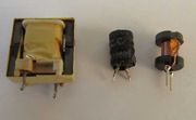
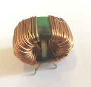
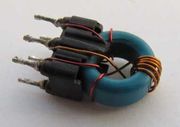
The smallest value inductors consist of no more than a coil of thick wire standing up from the circuit board. Some small inductors consist of a toroid of ferrite with the coil of wire wound around it, and are easily spotted. In others, the coil is wound around a ferrite core shaped like a cotton reel, which may be fitted snugly inside a hollow cylinder of ferrite. A common mode choke has two windings, sometimes used to filter both the live and neutral feeds to a power supply. This then is essentially no different from a transformer.
For large values of inductance a laminated iron core is used. This is rarely seen in reasonably modern equipment, but vintage valve radios often used two large capacitors and an iron-cored inductor to smooth the rectified mains.
An inductor frequently has no markings on it.
Fault-finding and Repair
There is very little to go wrong in an inductor apart from possibly a badly soldered joint. A very heavy current could cause an inductor to overheat or burn out, but probably not before much damage had been done elsewhere in the circuit.
Transformers
A transformer is simply an inductor with two (or more) coils of wire.
An electric current always creates a magnetic field which loops around the current, and a change in the magnetism looping through a circuit generates a voltage in that circuit. So in a transformer, we apply power to one coil of wire, the primary, and the magnetic flux which this creates induces a voltage in the other coil(s), the secondary(s). But it only works while the magnetic field is changing, and so a transformer can only be used for AC, not DC.
Transformers are very useful for two reasons:
- If the secondary coil has more or fewer turns than the primary, the voltage induced in it will be greater or less than that applied to the primary, in proportion.
- Since the only connection between the primary and the secondary is magnetic, they are electrically isolated from each other. This can be useful for safety reasons, or where the circuit designer needs to block a net flow of current from one part to another.
Identification
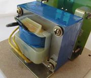
If you know how to identify an inductor, then a transformer looks exactly the same except that it has at least 3 wires coming out of it, and nearly always 4 or more.
Older mains powered electronic equipment almost always contains an iron cored mains transformer, which is easy to spot. Good quality audio equipment sometimes uses a toroidal mains transformer as this type produces less stray magnetic field and hence less background hum in the audio output. Newer equipment tends to use a much smaller transformer with a ferrite core.
Fault-finding and Repair
Mains transformers may be required to handle a substantial amount of power, and so in fault conditions they can become very hot. If this results in a breakdown of the insulation between two adjacent turns of either the primary or the secondary, these turns will act like a short-circuited secondary and become very hot indeed.
Rewinding a burnt out mains transformer is not difficult, but rarely would be worth the considerable time and patience required.
Crystals and Ceramic Resonators
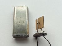
A quartz crystal is commonly used where the designer needs to generate a fixed frequency oscillation. Quartz is a piezoelectric material, which means that a voltage apears across opposite faces if you stress it, and conversly, applying a voltage causes a similar stress. A piece of quartz can be cut and polished so as to resonate (or ring like a bell) at a very precise chosen frequency. Placed in an electronic circuit which amplifies and sustains the resonance, you have a simple and very stable frequency source. The photo shows a crystal that has been removed from its protective can.
Apart from quartz clocks, digital equipment very commonly contains a crystal to provide the oscillation which steps it through its processing steps. In a digitally tuned radio a crystal oscillator generates a reference frequency from which the desired frequency is generated digitally in order to tune the chosen station. Some vintage FM radios contained three crystals in a glass envelope similar to a valve. This allowed three stations to be tuned by selecting one of the three crystals.
Ceramic resonators operate in the same way but are cheaper and less precise in their frequency. These generally use lead zirconium titanate instead of quartz and may be used instead of a crystal in digital equipment where the frequency is not also being used for precise timing. A ceramic resonator may also be used in the IF stages of a radio to select the required frequency. These resonators have 3 leads, one attached to each end of one face of the resonator, and the third attached to the opposite face. The signal is applied to the first and third, causing it to resonate along its whole length. The signal is reproduced between the second and third leads, with any other off-tune frequencies greatly reduced.
Identification
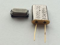
Quartz crystals are usually easy to spot as they come in a silvery metal can. In the case of quartz clocks they are usually cylindrical and quite small. Often, you will see two small capacitors adjacent to a crystal, which are required to allow it to vibrate freely. Occasionally, one of these might be a variable capacitor allowing a fine tuning of its resonant frequency, already accurate to around 10 parts per million.
A ceramic resonator looks very smilar to a small capacitor, except that it may have 3 or even 4 leads.
Fault-finding and Repair
Quartz crystals are usually reliable but failures are not unknown. Since the crystal itself is suspended only by its leads to allow it to vibrate freely it can be damaged by shock or vibration, perhaps combined with a weak joint resulting from a manufacturing defect.
There is no simple way of testing a quartz crystal apart from by substitution. A multimeter applied to its leads will show it as an open circuit since quartz is a very good insulator.
And now ...
... you might like to continue by reading about Active components.
